Thursday, September 4, 2008
Installing all of the probes
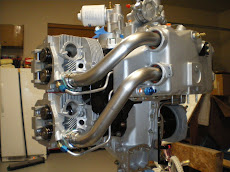
I have taken the time to install all of the engine probes from my JPI EDM-700. It's real nice doing it now of the engine stand because I can rotate it around in a circle and get at all of the parts. I drilled the exhaust pipes for the EGT probes and made sure that they are all the same distance down from the head. I called Don Rivera at AFP and am looking at getting my fuel injection kit today. You can tune your fuel injection once you start flying by adjusting the orfice size of your injector nozzles to each cylinder. With the 4 into 1 exhaust and doing the tuning, I should be able to dial my temps to within about a few degrees on one another. I did not tune my last engine and the temps are within 20 degrees most of the time. Thats still damn good and is almost not worth messing with. We'll see how this one works out. When I get my fuel injection kit I will document how this goes on. It's pretty neat to install one and it doesn't take a lot time. The hardest part is bending the lines for the nozzles and attaching them to the cylinders. You just have to make sure you don't kink them. I had a few that didn't match up to what Don had in the kit and he'll just send you one to your length. AFP is great company to deal with and they stand behind their stuff.
Wednesday, August 27, 2008
Been away for a while
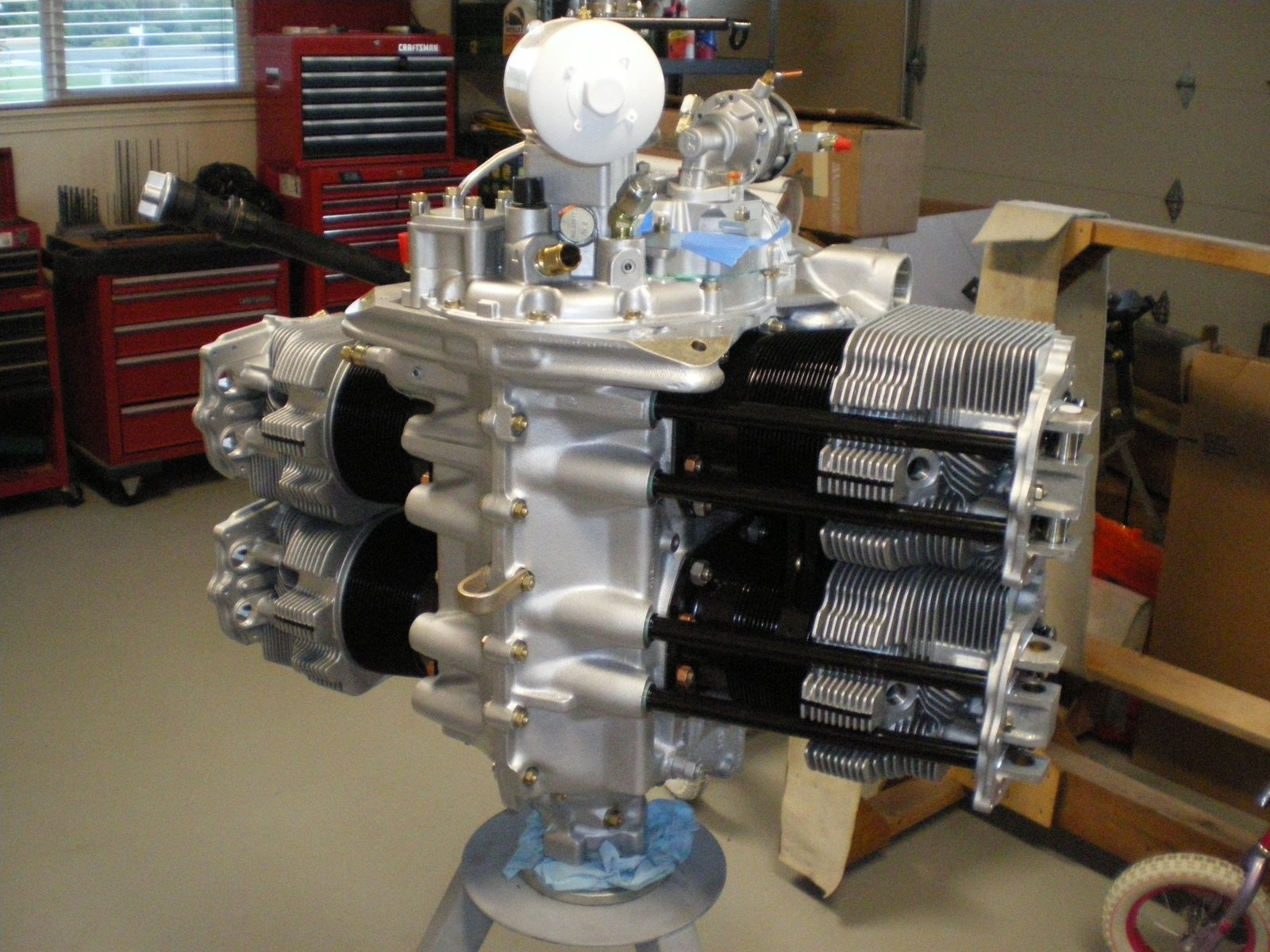
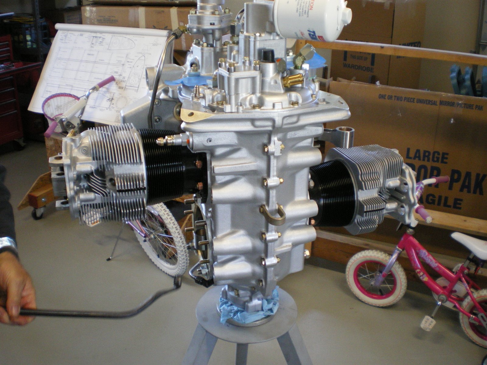
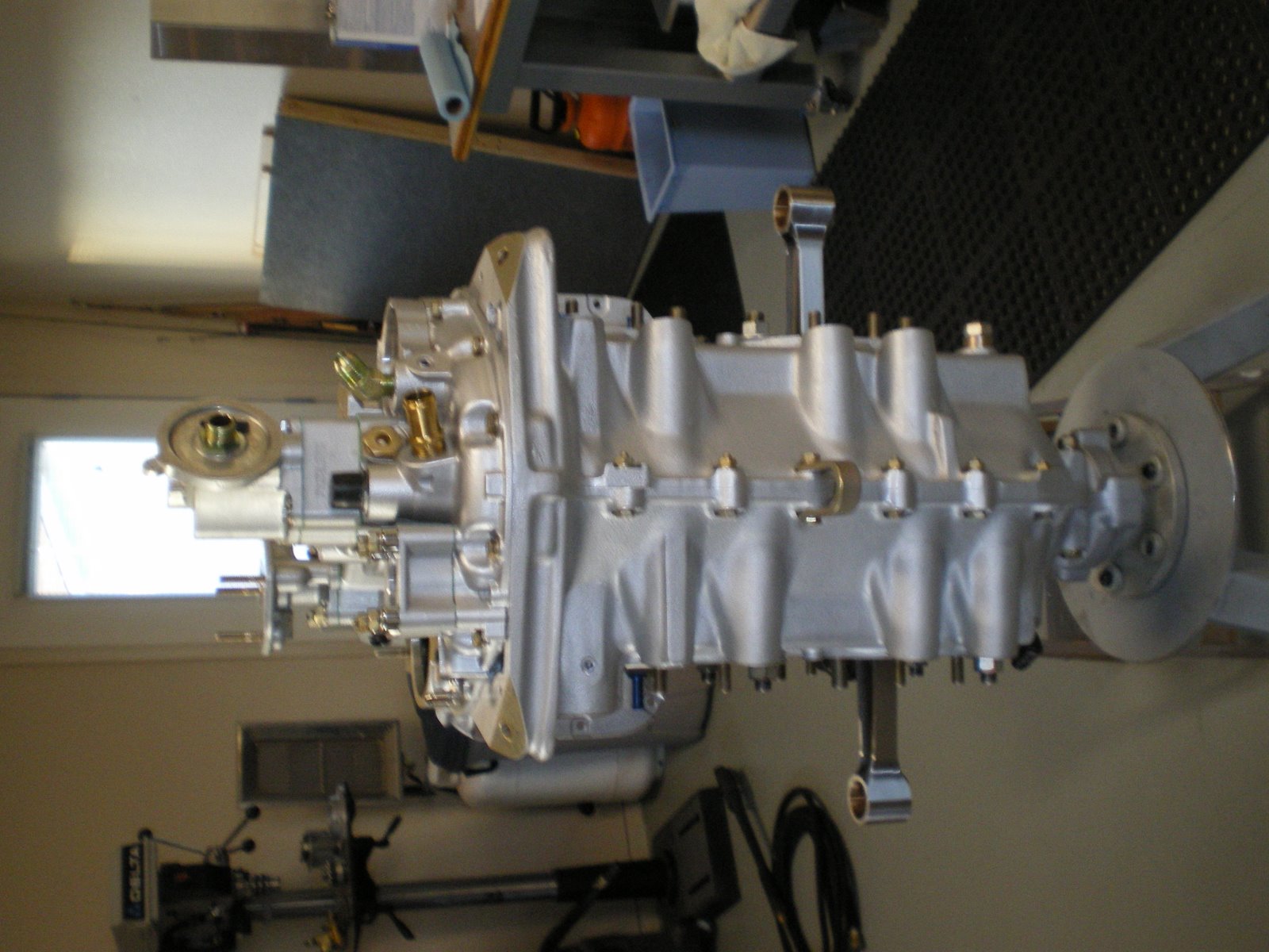
I have been working on the engine but I have also been on vacation. I have gotten the engine off the stand now and mounted to the horz stand that I can rotate it on. I have installed the rocker arm covers and spark plugs. Next is to mount the starter and alternator.
The starter is pretty straight forward. Just mount it and put on the four nuts, washer and lockwasher and torque it all down to 17ft/lbs.
The alternator is a different story. I already has the mounting brackets painted black. On my last engine I used the 40 amp alt. This engine will have the 60 amp alt. It has an internal volt regulator. It is smaller and more compact but there are other issues with it. You have to mess with the mounting a lot more to get it to fit. I bolted it up there on the brackets already bolted to the engine case. I saw right off that I was not in line with the ring gear. I was forward on the alt about 3/16 of an inch. I was able to use washers on the last alt to move it back and forth to get the line up. I cannot do that on this one. I get out the directions(typical male-mount first, read directions later) and find out that I have to slot the mounting bracket to move it aft. I had to take it off, sand blast it, have someone at work help me slot the holes, repaint it and remount it. That took about 3 days when it was all said and done back on the engine. I then had to mount the alt and get the alignment of the two pulleys and then torque it all down. Next comes the alt arm and cross brace to the starter. The alt arm I had to bend up to fit right and then you have to fab up a cross brace from the alt to the starter. This helpe brace the starter during a kick back.
You have to get the distance between the holes perfect to get it all to line up and fit. Once that was all done, I got out the right mag and timed it with the timing pin. Just rotate and drop the pin into the left rotation hole until it fall all the way in. Put #1 cyl on the compression strok at 25 degree BTDC and then insert mag. PUt on the retaining mounts and tighten it all down. I won't torque it all down until I get both mags on and time together. I still have to pull the spring on my impulse mag and turn it around. It came off and I mounted it back on in reverse. Go figure, I had a 50/50 chance of getting it right.
Saturday, August 23, 2008
Pushrods and Rocket covers
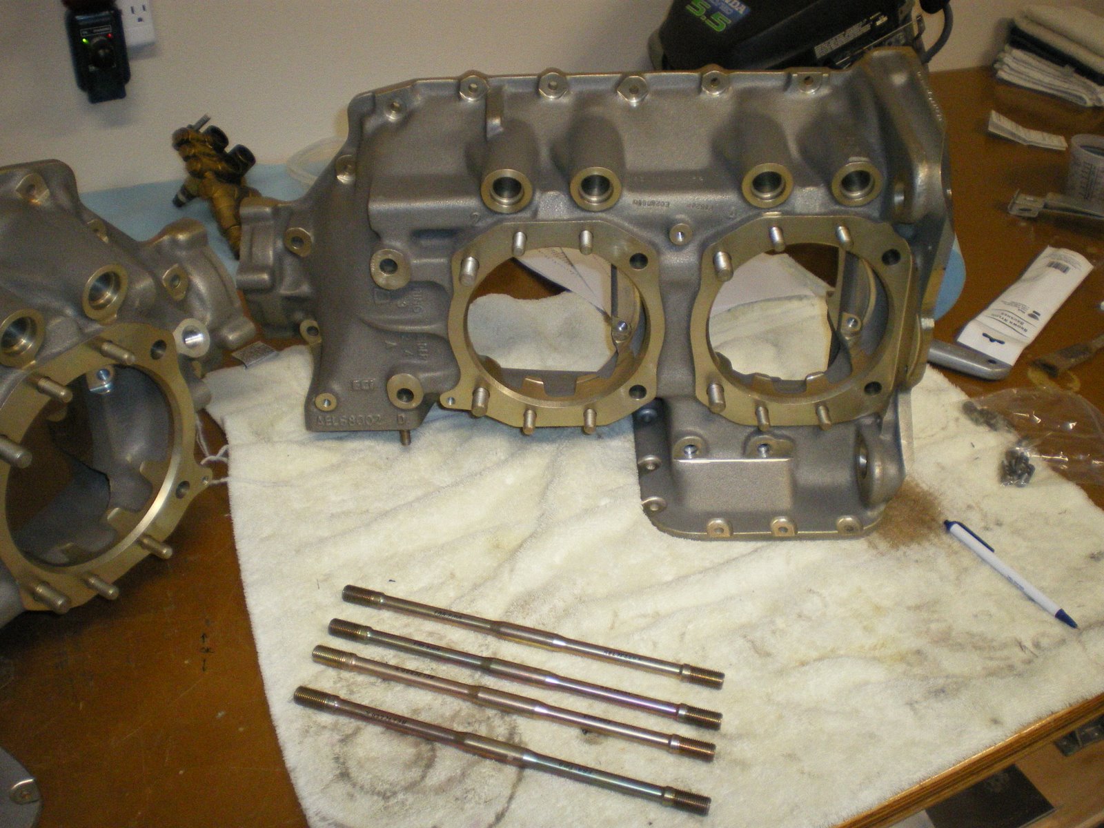
I have installed all of the pushrods on the engine. Aerosport has gotten me all of the -35 length pushrods I need. For some reason, all of the intake pushrods needed to be -35's and the exhaust one were -34's. That put all but one in the mid range of .050 clearance between the valve stem and rocker arm. I had one intake that was .035 clearance which is with in tolerance but that doesn't leave too much room since the min clearance is .028.
I purhcases some silicon rocker cover gaskets from Van's. I threw the cork gaskets away. They are leakers over time and you will back to installing silicon one. Pay atttention to the torque specs on the rocker cover screws with silicon gaskets. These are reusable gaskets. Covers are on and I have also installed the prop governor oil line. The clip they give you to hold the line down unders the cylinders is a little tight and pulls the line over too much. Looking through my pile of adel clamps, I found a longer one and installed it. It now is not in a bind at all. This will cut down on the stress of the line.
The engine is pretty much together now. I still have to install the mags, starter, and alt. I have to get the engine off the stand and mounted onto my horz rotating stand. I can put the front seal in and get the ring gear on. The front seal is always fun if it's not a split ring.
Saturday, August 9, 2008
Pushrods
I have called Aerosport and they say this is a common problem on brnad new engines. They will be sending me new 35's to do all of the intake rocker arms gaps. I had some older overhauled ones that look like they had the tips ground down a bit. I used them for trial fitting and they brought me down to .050 gaps. That's closer to the middle. I will be putting the new Lycoming ones in instead. This is a brand new engine and I will not have overhauled parts on it except for maybe the fuel injection servo. Not that overhauled parts are bad, it's just that I always wanted a new engine from the start. FedEx will have them to me by Monday morning and I will install on Monday afternoon. I will then get all of the valve covers installed and be ready to put on Mags. I still have to find out how many revolutions there is on the windup spring for the impulse coupling. Mine came undone and I have to wind it back up. After that the only thing left over will be the fuel injection system, starter and alt installations.
Tuesday, August 5, 2008
Installing rocker arms
I tried installing the rocker arms and push rods. I have all 73434 push rods. The 34 indicates the length of the rod. 35, 36,37 are all increasinsly longer. They make these for overhauled engines that need longer rods to make up for material that has been ground off camshafts and tappets. I installed them by oiling down the push rods first. I took a syringe and sucked oil up into it. I then have a blunt needle that I put on and inject oil down inside the push rod. This gets some oil in there for startup and keeps out the corrosion out. I insert the rod into the tube and then set whatever cylinder I am working on at TDC on the compression stroke. I take the lubed up rocker arms and install the by pushing down on the push rod with the rocker arm and getting the rocker arm shaft lined up with all of the holes. It sounds easy but is harder when everything is lubed up and slick. Once both intake and exhaust are done it's get out the feeler gauges and check clearances on the arm to the stem/or cap. It needs to be >.028 and <.080. All of my intakes are over .080. Something is wrong. Lycoming used to have two styles of rocker arms, one for exhaust and one for intake. ECI sent one length of rods and one style of rocker arms. On a new engine I should not have over .080 valve clearance. I sent Aerosport a e-mail to see if I am doing it wrong or don't have the right parts. All of my other engines are flying around fine. Granted they were overhauled and I had to buy different lengths of pushrods. This is engine building and you have to do whatever it takes to make it right. So for now I will sit and wait. Maybe even have a beer!
Installing all of the stuff under the cylinders
I have installed the intercylinder baffles. The are a major PITA to get on without scratching the paint on the fins. I got the tapered fin barrels and I thing that was a mistake. The baffles did not fit well and I had to grind off some material near the base and bend the heck out of the thing to get it to fit around the base. I also RTV'd the ledges of the baffles so they don't wear on the fins. I have pulled apart to many that were toasted from the fins wearing on the baffles. I installed the oil line drain tubes and I had to bend on those to get them to clear the bottom of the cylinder fins. Some things never change. Bash to fit, paint to match. I then installed the intake tubes. I learned my lesson on the last engine with the big 0-rings on the tubes. Lube up the o-rings and the inside of the plenum tube. Slowly rotate the intake pipe into the the plenum tube being careful not to push it in too hard. If it goes all the way into the plenum, you have to pull it back out. This will pinch or cut the o-ring and you'll have to drive all the way into town to get another one if you have a hydraulic shop close by. Some of the intake pipes fit pretty tightly to the bottom of the oil pan. They don't hit but don't miss by much either. I though I have it wrong but the tubes only can fit into one hole. Once this was all done I got all of the push rod tubes installed. Same thing here, lube the o-rings that go into the cylinder head. Pull the tubes while rotating at the same time and use a long socket that is the same diameter as the push rod tube to help push it in. It should kind of pop into place and you will not be able to push it farther. BTW, did I mention that you should install the plungers inside the tappets before you put the tubes in place. Don't fill them with oil because you will need to test for rocker arm gap once the rocker arms are installed. They will hydraulically load up and you will not be able to compress them.
Monday, August 4, 2008
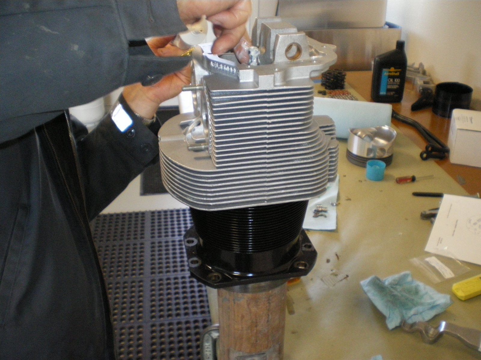
Installing the cylinders
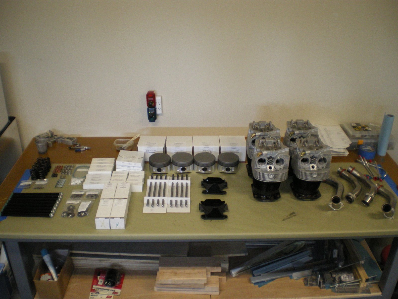
We installed the cylinders on the engine today. I started out by getting the bench all cleaned up and organized. I logged all of the lot numbers on my parts sheet that will be loaded into the computer later on so I have a computer file of my engine parts that can be accessed at whim. I also got out the tools needed to put the cylinders together.
Torque wrenches, cylinder wrenches, ring compressor, rign expander pliers, valve compressor, picks, magnet on a stick (for valve keepers), flashlight and more. Get all of the this stuff ready to go because when you start compressing valves it needes to be a quick reach.
We start off by putting the valves in the cylinders. Clean the guides, lube the stems and install making sure not to scratch the valve stems. Remember earlier, I lapped the valves and kept the cylinders and valves together. I mounted our hi-tech valve keeper-inner on the bench which is a post with angles on it and the top has been rounded. I clamped it to the bench and when you get your valves in place you hang onto the stems and have someone pick up the cylinder. You lower it down onto the post and this will help keep the valve seated while you push down on them with the spring compressor. Next you oil up the valve seats top and bottom. There is not a difference on the bottom ones but there is on the top. The cone shape one goes on the intake stem. Get your springs out and lube them up and make sure they are the right way facing up. Put them on the seat over the stem and install the top seat. Install the rocker arm shaft and take your brand new valve spring compressor and push the springs down. This a two person job. One person holds onto the cylinder and does the compressing. The other person guides the top seat over the stem so it does not scrap the valve stem. Have you keeper ready to go and install. The exhaust ones are like half shaped circles. You put them in under the hole in the spring compressor (there a arc in it for this purpose) with your screw diver. You put one in and then rotate it around to back side. Install the other opposing it and then slowly let off on the spring. It should push the keeper up and seat it in the groove in the stem. DON'T let the keeper turn up or down it has to lay in there flat. Once that it done move onto the intake steam. These keepers are a little different in that they are more cone shaped. I used some Lubraplate and put some on the inside of the keeper. This holds it onto the stem while you let up on the compressor. Compress the spring and take your magnet and put the keeper on it pointing down. Lower it down into the compressor hole and then use a pick or small screw driver to push it off the magnet and push it up against the stem. There is a notch in the stem and curb on the keeper, so you will feel it go into place. Do the same for the other side. Once they are both done and oppose one another, slowly raise the compressor and it will seat the keepers on the stem. If the keepers are cocked or look wrong then put the pressure back on the compressor and adjust them until they seat. By the 4th cylinder your a pro. They have special tools besides the compressors that make all of this easy. However, this is on the cheap so we are doing it the harder way. Use lots of oil and snot to coat things up. Once you are done, put the cylinder in a box upside down to drain off excess oil into a rag. This will keep it all from running down the engine on the stand.
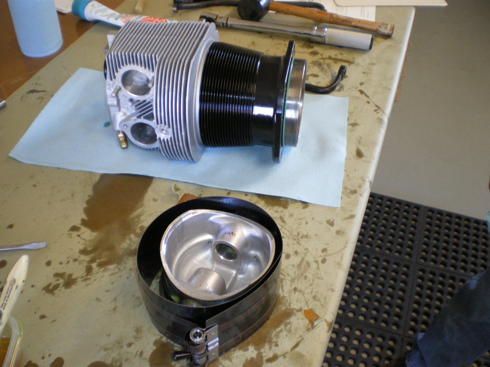
Once all 4 cylinders are done, start with the rings on the piston and install it in the cylinder. The rings are clearly marked and there is a bulletin on ECI website that gives you clearances and ring gap orientation. We checked ring gap and top stroke and it was above the .0075 min. We lubed up the rings and installed them on the cylinder. The top and bottom ring gaps are lined up with the middle ring gap is 180 degress opposite of it. Superior has them at 10 and 2. Why, I have no idea. Once that is done lube up the cylinder walls with MINERAL oil and make sure there is not grit in there. Lube up the piston and put the compressor on it. Compress the rings making sure not the turn them, put the piston over the cylinder bore and push the piston out a bit just so the top sticks out. Push this chamferred area into the bore and them push the piston down into the bore. Make sure you oriented the piston to go it with the wrist pin holes pointing the right way. You don't want to turn the piston anymore than you have to. Only insert the piston into the bore enough so the rings don't come out. Get your cylinder wrist pin lube up and then start it into the piston. Take the cylinder over to the engine and install it on the engine. We installed the #2 cylinder first because these are the first thru studs that get torqued in the sequence. Install the bottom o-ring seal on the cylinder before you put it on. Take the cylnder over to the engine, have someone line up the wrist pin the con rod and slide it thru. Then push the cylinder down onto the studs and install the hold down nuts. THERE IS THREE SEQUENCES TO FOLLOW. 1. The case torque sequence 2. The big cylinder hold down nuts 3. The little cylinder hold down nuts. So do each cylinder as you need to for the case/thru bolt sequence then torque each one as the manual shows. We did not torque the big hold down nuts on cylinders to full 600 in/lbs until we had all cylinders on the engine. Once they are all on, torque to full amount using the torque sequence in the manual. Don't worry if you hear some squeaking noises when you torque the big nuts on the thru bolts. They are just stretching a bit. I go through the sequence twice and give a little time between cycles. You'll be suprised how much the thru bolts stretch on the second cycle. Once this is all done you can start installing the rest of the stuff as follows.
1. Intercylinder baffles.
2. Cylinder oil drain tubes.
3. Intake tubes.
4. Push rod tubes,
5. Push rod retainers with lock plate.
By this time you will have oiled everthing down in your shop including yourself. Probably have all of your tools out and have gone through about 3 rolls of paper towels. Enjoy.
Torque wrenches, cylinder wrenches, ring compressor, rign expander pliers, valve compressor, picks, magnet on a stick (for valve keepers), flashlight and more. Get all of the this stuff ready to go because when you start compressing valves it needes to be a quick reach.
We start off by putting the valves in the cylinders. Clean the guides, lube the stems and install making sure not to scratch the valve stems. Remember earlier, I lapped the valves and kept the cylinders and valves together. I mounted our hi-tech valve keeper-inner on the bench which is a post with angles on it and the top has been rounded. I clamped it to the bench and when you get your valves in place you hang onto the stems and have someone pick up the cylinder. You lower it down onto the post and this will help keep the valve seated while you push down on them with the spring compressor. Next you oil up the valve seats top and bottom. There is not a difference on the bottom ones but there is on the top. The cone shape one goes on the intake stem. Get your springs out and lube them up and make sure they are the right way facing up. Put them on the seat over the stem and install the top seat. Install the rocker arm shaft and take your brand new valve spring compressor and push the springs down. This a two person job. One person holds onto the cylinder and does the compressing. The other person guides the top seat over the stem so it does not scrap the valve stem. Have you keeper ready to go and install. The exhaust ones are like half shaped circles. You put them in under the hole in the spring compressor (there a arc in it for this purpose) with your screw diver. You put one in and then rotate it around to back side. Install the other opposing it and then slowly let off on the spring. It should push the keeper up and seat it in the groove in the stem. DON'T let the keeper turn up or down it has to lay in there flat. Once that it done move onto the intake steam. These keepers are a little different in that they are more cone shaped. I used some Lubraplate and put some on the inside of the keeper. This holds it onto the stem while you let up on the compressor. Compress the spring and take your magnet and put the keeper on it pointing down. Lower it down into the compressor hole and then use a pick or small screw driver to push it off the magnet and push it up against the stem. There is a notch in the stem and curb on the keeper, so you will feel it go into place. Do the same for the other side. Once they are both done and oppose one another, slowly raise the compressor and it will seat the keepers on the stem. If the keepers are cocked or look wrong then put the pressure back on the compressor and adjust them until they seat. By the 4th cylinder your a pro. They have special tools besides the compressors that make all of this easy. However, this is on the cheap so we are doing it the harder way. Use lots of oil and snot to coat things up. Once you are done, put the cylinder in a box upside down to drain off excess oil into a rag. This will keep it all from running down the engine on the stand.
Once all 4 cylinders are done, start with the rings on the piston and install it in the cylinder. The rings are clearly marked and there is a bulletin on ECI website that gives you clearances and ring gap orientation. We checked ring gap and top stroke and it was above the .0075 min. We lubed up the rings and installed them on the cylinder. The top and bottom ring gaps are lined up with the middle ring gap is 180 degress opposite of it. Superior has them at 10 and 2. Why, I have no idea. Once that is done lube up the cylinder walls with MINERAL oil and make sure there is not grit in there. Lube up the piston and put the compressor on it. Compress the rings making sure not the turn them, put the piston over the cylinder bore and push the piston out a bit just so the top sticks out. Push this chamferred area into the bore and them push the piston down into the bore. Make sure you oriented the piston to go it with the wrist pin holes pointing the right way. You don't want to turn the piston anymore than you have to. Only insert the piston into the bore enough so the rings don't come out. Get your cylinder wrist pin lube up and then start it into the piston. Take the cylinder over to the engine and install it on the engine. We installed the #2 cylinder first because these are the first thru studs that get torqued in the sequence. Install the bottom o-ring seal on the cylinder before you put it on. Take the cylnder over to the engine, have someone line up the wrist pin the con rod and slide it thru. Then push the cylinder down onto the studs and install the hold down nuts. THERE IS THREE SEQUENCES TO FOLLOW. 1. The case torque sequence 2. The big cylinder hold down nuts 3. The little cylinder hold down nuts. So do each cylinder as you need to for the case/thru bolt sequence then torque each one as the manual shows. We did not torque the big hold down nuts on cylinders to full 600 in/lbs until we had all cylinders on the engine. Once they are all on, torque to full amount using the torque sequence in the manual. Don't worry if you hear some squeaking noises when you torque the big nuts on the thru bolts. They are just stretching a bit. I go through the sequence twice and give a little time between cycles. You'll be suprised how much the thru bolts stretch on the second cycle. Once this is all done you can start installing the rest of the stuff as follows.
1. Intercylinder baffles.
2. Cylinder oil drain tubes.
3. Intake tubes.
4. Push rod tubes,
5. Push rod retainers with lock plate.
By this time you will have oiled everthing down in your shop including yourself. Probably have all of your tools out and have gone through about 3 rolls of paper towels. Enjoy.
Monday, July 28, 2008
Going backwards!
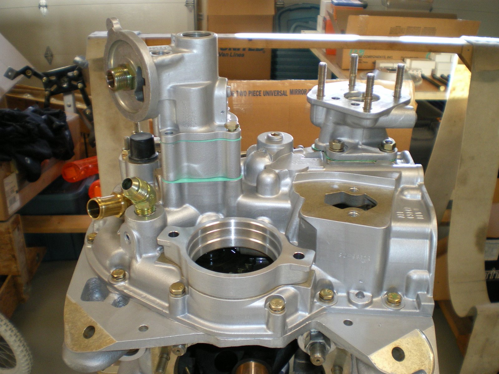
I was reading through the ECi supplements and I came across one for the oil pump body. It says that the little hole on the side of the pump needs to be plugged up if you don't have fuel pump gears to lubricate. For the life of me, I cannot remember if I checked that or not. I took pics of the pump but only when it was mounted on the assy case and safetied wired. So I decided to take the assy case of and double check. It only took about a half hour to get the parts off the assy case and sump off. I double checked the pump and there was no hole at all so I was in the clear. Now I am telling you all of this because this is a lesson in learning to build engines. I would rather spend a half day pulling apart my engine to double check something just to be sure than spend the rest of my life dead because I have my pride. Swallow your pride and get out the wrenches. My family will be flying with me and I need to have that confidence that I did everything right. I put all of the parts back on the engine and I have peace of mind. I also read through all of there bulletins and checked to make sure there was nothing else that I missed.
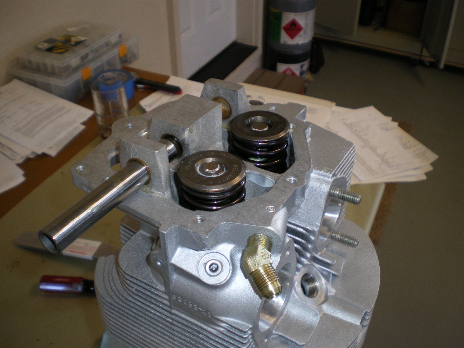
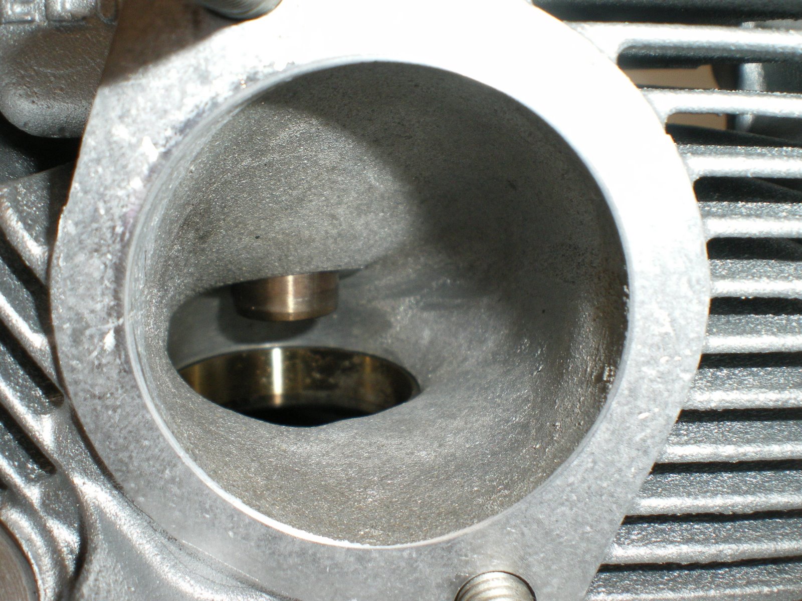
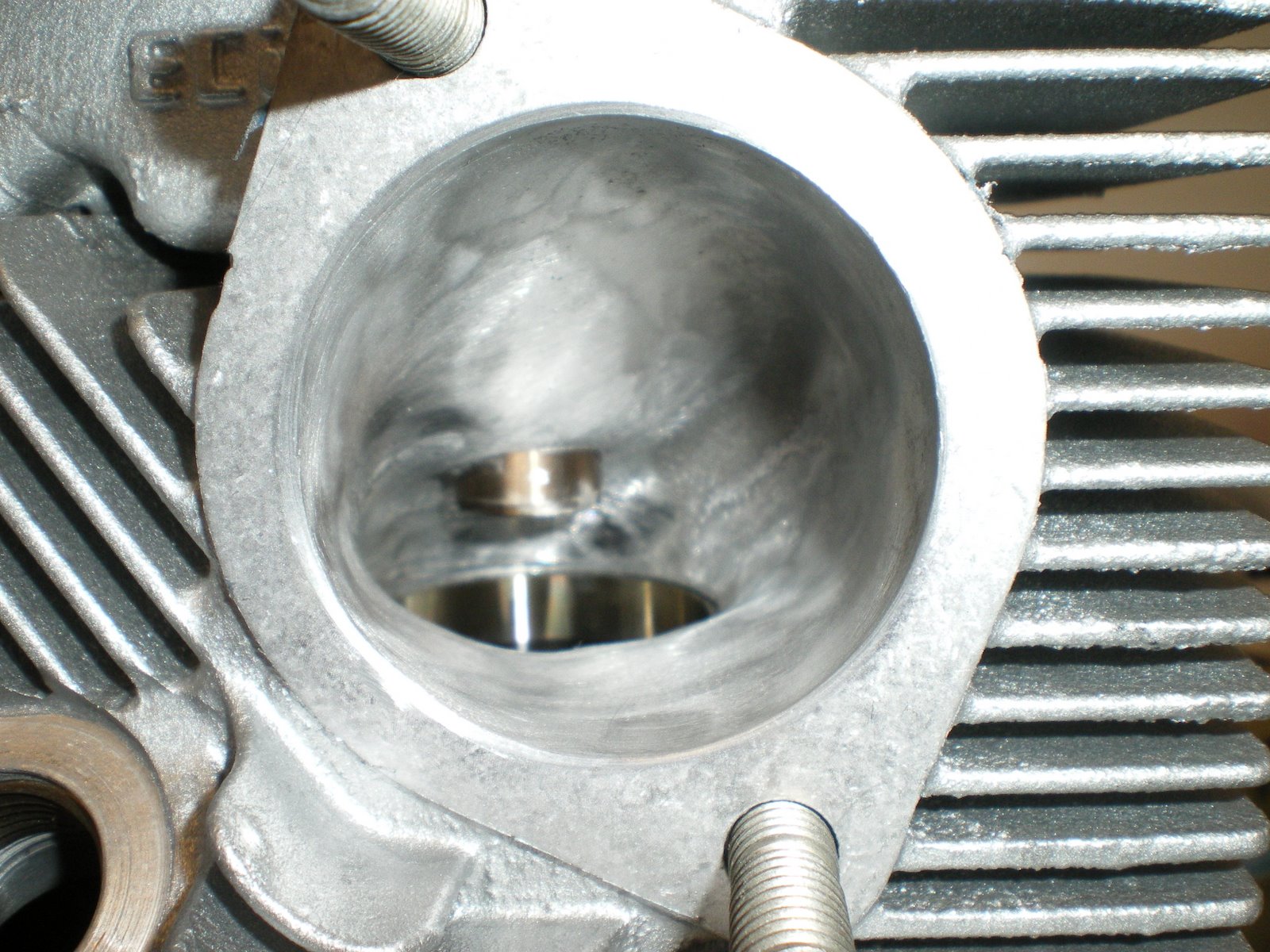
I am still waiting on my spring compressor to arrive and small flap wheel so I can finish polishing those ports in the hard to reach areas. I also am trying to figure out how the valve springs go on the cylinder heads. There is a inner and outter valve spring and there is a top and bottom to the spring itself. It's very hard to tell, but they said the double coil is supposed to go towards the bottom. Now maybe I am not seeing this but there is not double coil. The only difference I can see is that one of the sides is not as tapered down as the other. Called ECI and sent a picture so they could inform me which way it goes. They seem to be very helpful and are working on it as I write this blog. I will get back and let you know what is going on. A picture is posted to let you decide what is up and what is down.
I am still waiting on my spring compressor to arrive and small flap wheel so I can finish polishing those ports in the hard to reach areas. I also am trying to figure out how the valve springs go on the cylinder heads. There is a inner and outter valve spring and there is a top and bottom to the spring itself. It's very hard to tell, but they said the double coil is supposed to go towards the bottom. Now maybe I am not seeing this but there is not double coil. The only difference I can see is that one of the sides is not as tapered down as the other. Called ECI and sent a picture so they could inform me which way it goes. They seem to be very helpful and are working on it as I write this blog. I will get back and let you know what is going on. A picture is posted to let you decide what is up and what is down.
Thursday, July 24, 2008
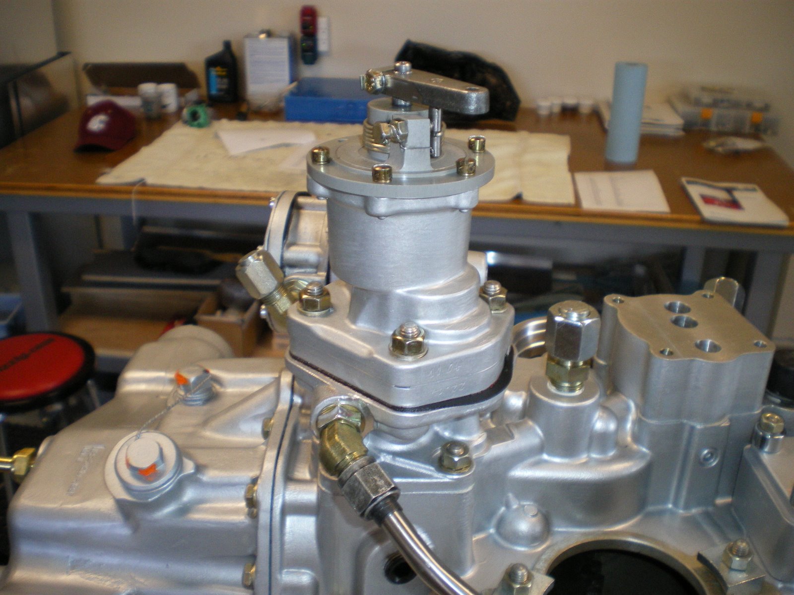
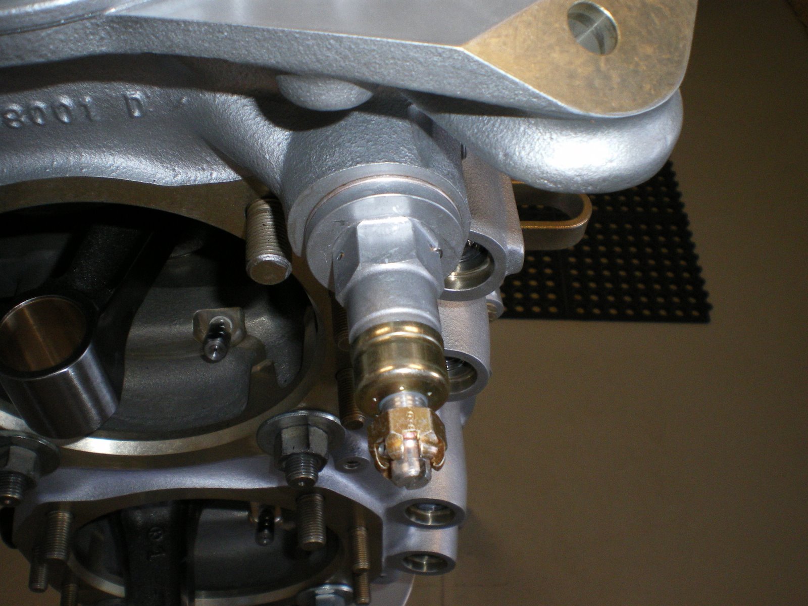
Fitting all of the fittings--Son of a #@%&$
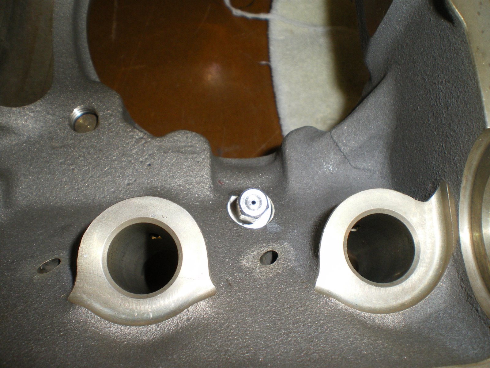
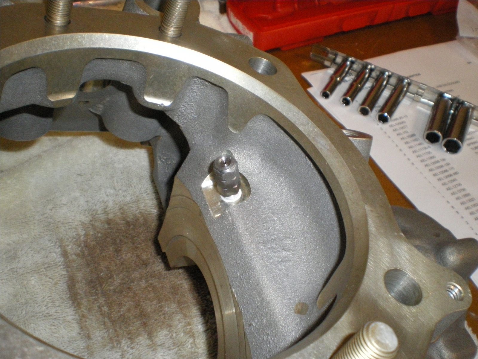
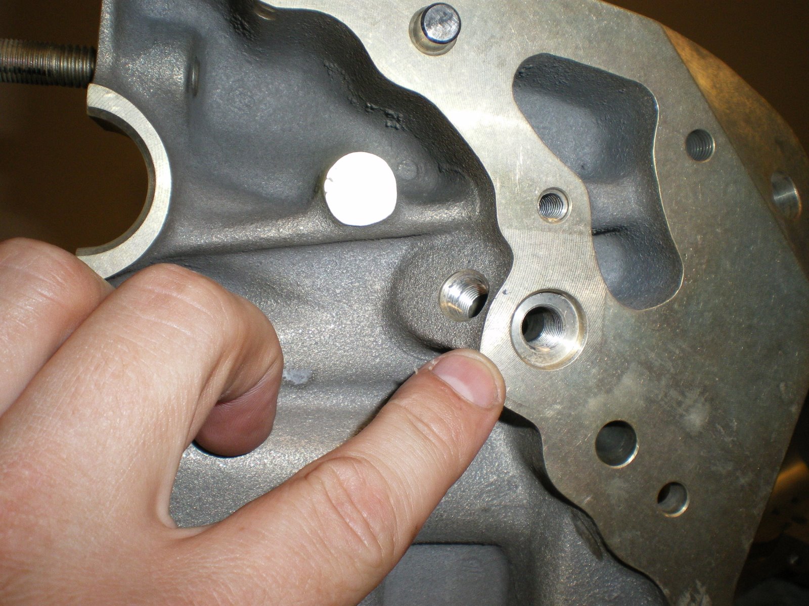
Part of the fun of putting together your own engine is finding out what does not want to fit. I am working on the oil cooler bypass fittings and the tach drive. I used the oil cooler bypass fittings before in my other RV-6. It's a special banjo fitting with special seal washers to seal the two sides of the banjo fitting. There are several reasons to use this style of fitting. One is that is can be rotated 360 degrees. So making oil lines fit up to it is very easy. The other is keeping all of the fittings up near to the top of the engine where they can be seen. The other oil line plug is down between the mags and is a little harder to get it. Plus it's more oil line to route and weighs more. The downside to using the banjo fitting is that it's a special thread 5/8-16. They is a special Cessna fitting that can be purcahsed if you don't mind paying 150 bucks for it. I have gotten surplus fittings from the days of old from Jesse at AERO. I cannot use the fitting since it's too close to the oil filter housing. The 90 degree oil filter solves one problem but creates another. I also have an issue with the Van's Tach that I am trying to use. I got the kind for the engine that is for ones without vacuum pumps. I will have to get one for ones with vacuum pumps that is a cable and mounts on the firewall. I had this on my last airplane and it works. It's just one more thing to mount of the firewall. I have also installed the new oil line fitting that goes in between the mags. I will use this one (as most others do as well) to supply oil to my cooler. I have also installed the 5/16 studs for the fuel injection servo on the sump. Studs are used here becasue there is no room for bolts. I have also finished polishing my ports on the cylinder heads for now. I am waiting for some smaller flap wheels to come in so I can get in there in the tight places. I will try and post some pics of the problems I face tomorrow.
Wednesday, July 23, 2008
Putting the mag gears on.
I tried to install one of the mag gears on the mag that has the impulse coupling on it. I took off the nut and went to put on the gear when the impulse coupling came up and unwound a couple of turns. This thing is spring loaded and there is a correct number of convolutions to keep the exact amount of tension on the impulse coupling. A quick call to my Dad and he had a overhaul book for Slick mags. I will get this from him when he comes up to help me get the cylinders on. Trying to get the gears torqued down while keeping them from spinning is going to be hard. There is a pin that comes with the mag but that is to hold the mag gear from moving after you have it timed and are installing it into the engine. It is not sturdy enough for me to torque it. More to follow.
Working on the cylinders
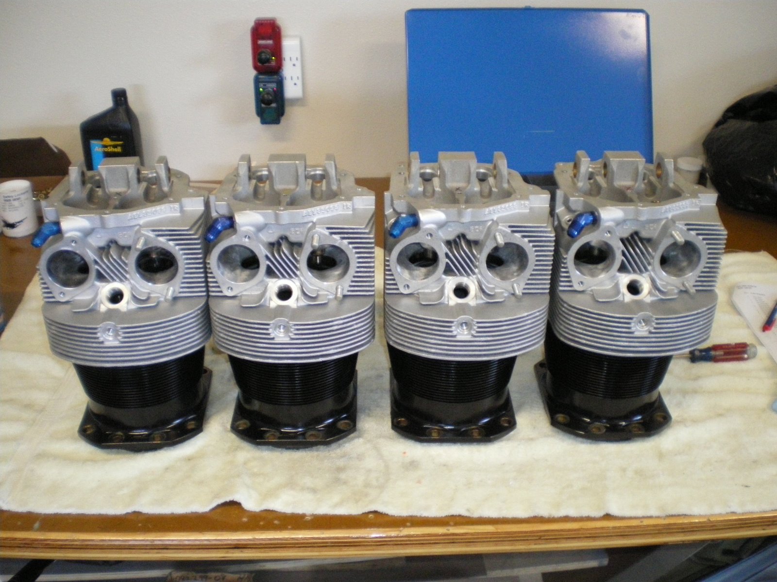
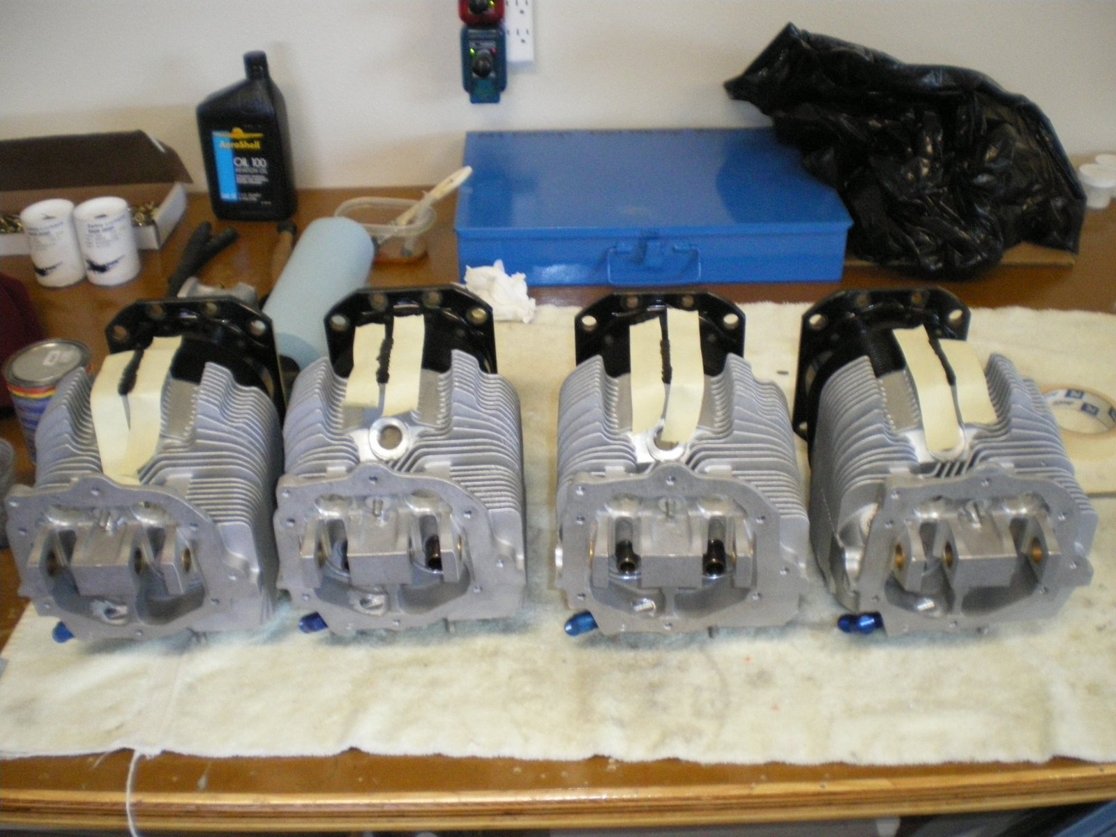
I started working on the cylinders. I have painted the top aluminum heads silver. I used the 3M cup system to spray the cylinders so that I could paint upside down. It worked ok but the paint came out in blotches. I had to take a brush and brush out the heavy spots. I thinned the paint down with reducer but it was not enough. It says 20% but it should be more like 30% and use a fast reducer.
After the top was painted I started on the bottom. Having problems with the top I had the local paint shop put some of my enamel in a spray can. They take my paint and put it in a spray can. It already has the solvents in it and it makes clean up a snap. I masked off the top and the lower portions so paint would not get on then and then took the cylinders outside and spray each one individually. They came out nice.
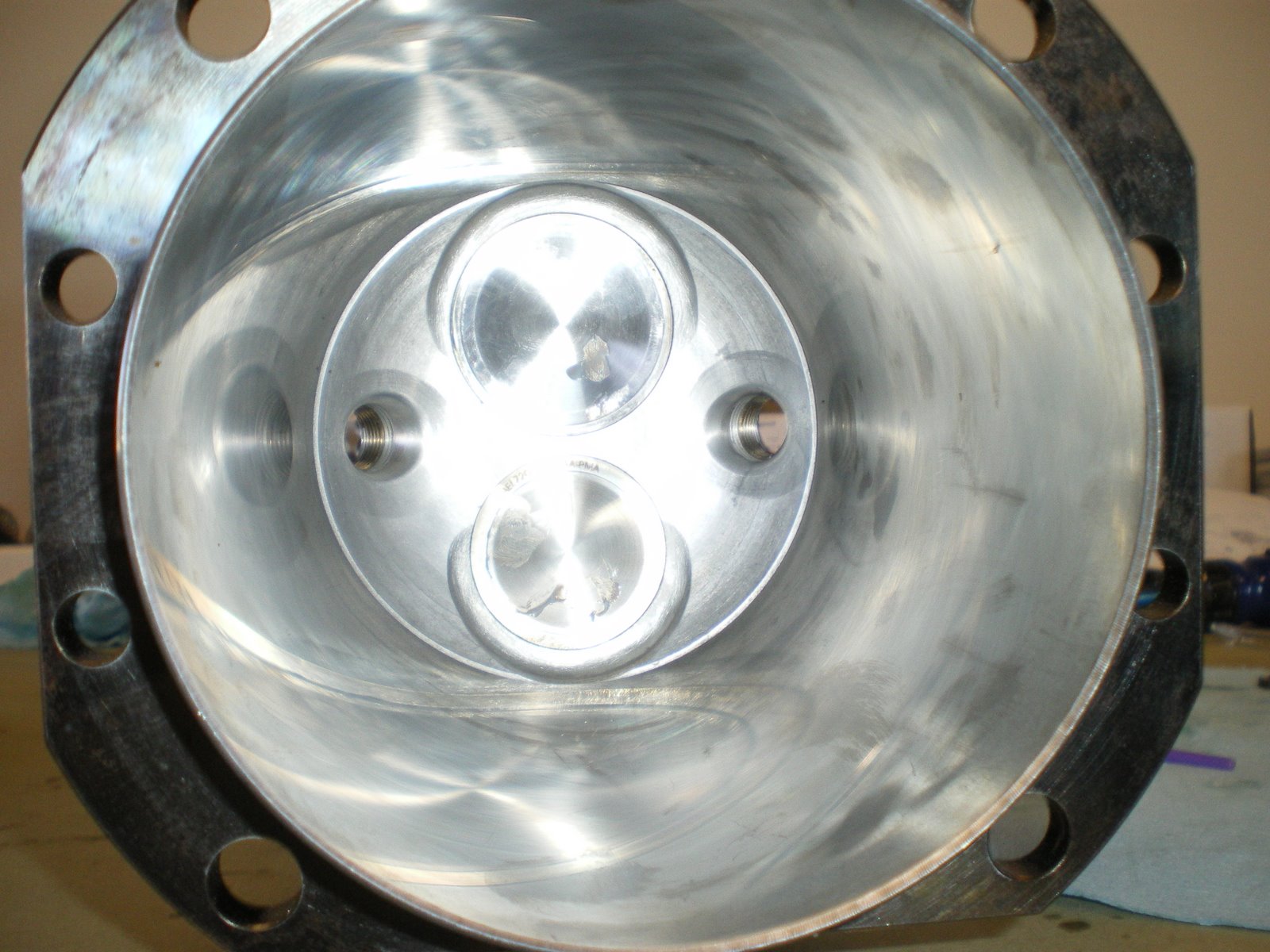
Next I am doing some grinding on the intake and exhaust ports. I have taken pictures of the sand casting in the ports and some of it is pretty rough. I have gotten cylinders from Ly-Con before and there porting is a work of art. They also produce the power as well. I just wanted to grind out imperfections and blend it all smooth. I could not reach all of the areas as you have to have some special grinding wheels to get in all of tight spots. I got about 80% of each port. I also had to be careful not to grind the seat for the valves. That would be very very bad. After I ground each cylinder I would clean it up and then lap the valves to the seats.
I talked with Ken Tunnel once about porting cylinders. He said all of his dyno testing indicated that the Lycoming cylinder worked out the best for porting. It always made more power. He has done Superior and ECI and indicated they never made the same power as Lycoming. I was in the shop one day getting my cylinders and he had a set ready to go for Sean Tucker for his Oracle bi-plane. They were Lycoming. Not saying ECI is bad, but something about there port design does not let the air flow the same. Call it BS but he has hard dyno testing to prove it. My cylinders with all of the mods to the engine should get me over 190 hp. If it puts out 195 with the 4-1 exhaust and the ram air cowling, I would be really happy.
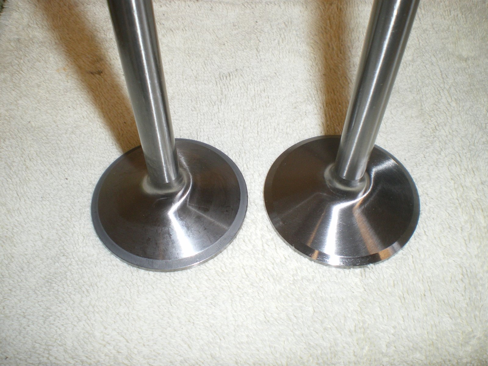
I read up on lapping valves and there is not much too it. I purchased all of the items to lap valves at the local auto shop for about 20 bucks. You get some fine lapping compound, a lapping tool which is two suction cups on a stick, and a buncn of rags. I used some hose and extended the lapping tool so that it would stick up out of the cylinder a ways.
The valves in the cylinder cannot be mixed up. One is big (intake) and one is small (exhaust). I installed one on the end of the lapping tool, put compound on the seat of the valve , greased the stem and then installed it in the cylinder. I then set the cylinder up on the bench (inverted) let it lean against my chest. I then would spin the lapping tool back and forth like you are trying to start a fire. You need to hold a little down pressure as well. You can hear the valve lapping as it grinds. The grinding will start to go away and you will hear more of a smearing noise (you can feel it as well). This tells you that the valve is lapped and it completely seated in the valve seat. Take the valve out and clean it all up. Clean the seat as well. I then marked the cylinder a color and the both valve went into a valve box that was also marked the same color. This system will keep me from mixing up vavles cylinder to cylinder. Also when you look at the valves, you can see a slight graying of the valve where it hit the seat. The lapping compound it black and this help dye the area as it is ground down.
I purchased a Lycoming valve spring compressor from US Tools for 60 bucks. When I get that I will start putting the cylinders together for good and mounting them on the lower half of the engine.
After the top was painted I started on the bottom. Having problems with the top I had the local paint shop put some of my enamel in a spray can. They take my paint and put it in a spray can. It already has the solvents in it and it makes clean up a snap. I masked off the top and the lower portions so paint would not get on then and then took the cylinders outside and spray each one individually. They came out nice.
Next I am doing some grinding on the intake and exhaust ports. I have taken pictures of the sand casting in the ports and some of it is pretty rough. I have gotten cylinders from Ly-Con before and there porting is a work of art. They also produce the power as well. I just wanted to grind out imperfections and blend it all smooth. I could not reach all of the areas as you have to have some special grinding wheels to get in all of tight spots. I got about 80% of each port. I also had to be careful not to grind the seat for the valves. That would be very very bad. After I ground each cylinder I would clean it up and then lap the valves to the seats.
I talked with Ken Tunnel once about porting cylinders. He said all of his dyno testing indicated that the Lycoming cylinder worked out the best for porting. It always made more power. He has done Superior and ECI and indicated they never made the same power as Lycoming. I was in the shop one day getting my cylinders and he had a set ready to go for Sean Tucker for his Oracle bi-plane. They were Lycoming. Not saying ECI is bad, but something about there port design does not let the air flow the same. Call it BS but he has hard dyno testing to prove it. My cylinders with all of the mods to the engine should get me over 190 hp. If it puts out 195 with the 4-1 exhaust and the ram air cowling, I would be really happy.
I read up on lapping valves and there is not much too it. I purchased all of the items to lap valves at the local auto shop for about 20 bucks. You get some fine lapping compound, a lapping tool which is two suction cups on a stick, and a buncn of rags. I used some hose and extended the lapping tool so that it would stick up out of the cylinder a ways.
The valves in the cylinder cannot be mixed up. One is big (intake) and one is small (exhaust). I installed one on the end of the lapping tool, put compound on the seat of the valve , greased the stem and then installed it in the cylinder. I then set the cylinder up on the bench (inverted) let it lean against my chest. I then would spin the lapping tool back and forth like you are trying to start a fire. You need to hold a little down pressure as well. You can hear the valve lapping as it grinds. The grinding will start to go away and you will hear more of a smearing noise (you can feel it as well). This tells you that the valve is lapped and it completely seated in the valve seat. Take the valve out and clean it all up. Clean the seat as well. I then marked the cylinder a color and the both valve went into a valve box that was also marked the same color. This system will keep me from mixing up vavles cylinder to cylinder. Also when you look at the valves, you can see a slight graying of the valve where it hit the seat. The lapping compound it black and this help dye the area as it is ground down.
I purchased a Lycoming valve spring compressor from US Tools for 60 bucks. When I get that I will start putting the cylinders together for good and mounting them on the lower half of the engine.
Saturday, July 19, 2008
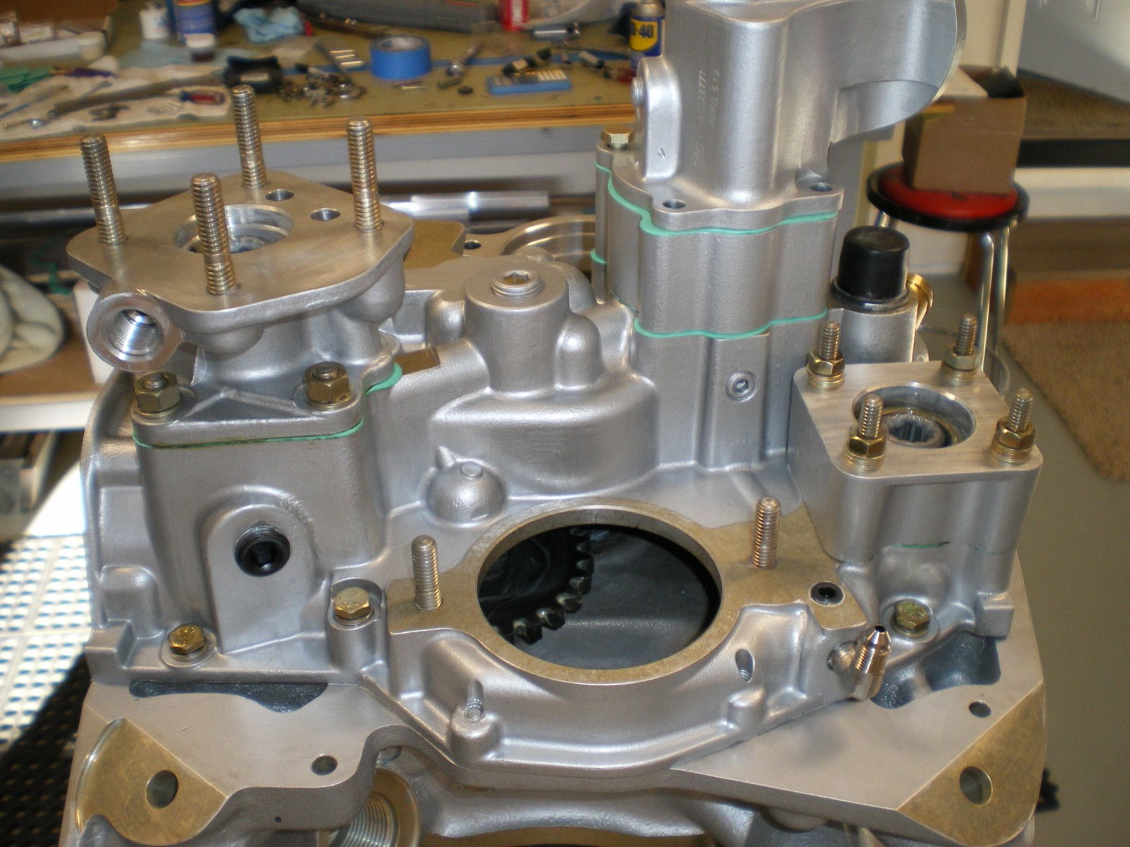
Installing the sump
After all of the assy case stuff is where it needs to be, I installed the sump. I have already installed the screen and plug, sniffle valve and oil drain valve prior to this. I checked over my safety wire jobs on the bottom bolts and got to putting the gasket sealant on the case. I also installed the 6 studs that go into the sump in the area under the cylinders. There is studs here so you can use nuts in the confined space instead of using bolts. There is sixteen bolts and 6 nuts to hold the sump down. I had to get some of my own bolts since they were not in the kit. I called Aerosport and they are sending some ASAP but my grade 8 bolts 1 inch long will do fine in this spot. I took some precaution when I installed the studs into the sump. They were an extremely tight fit and I was afraid of breaking the stud off trying to get it down into the threads with the double nuts on. I took a tap and tapped out the all six holes. I know they want a tight fit so the nut does not turn when you tightnen it down. I used some high strength Locktite on the threads and installed them. I did not torque these nuts down until the next day. I only had one turn on me and I marked it. I will check it later and see how it goes.
Installing all of the assy drives.
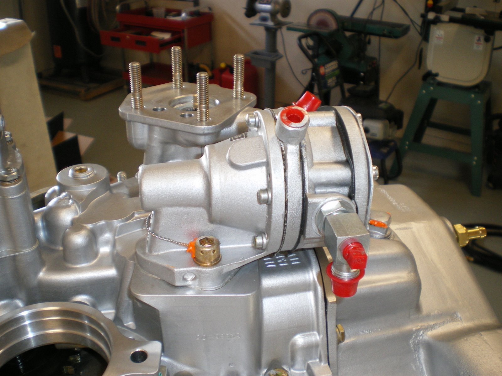
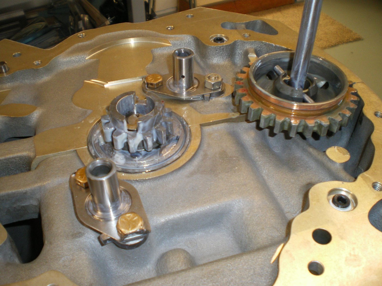
I installed the vac pump, gov drive, and fuel pump today. I tried to see if the fuel pump diaphragms were ethonal compatible but Tempest says they are not. I looked for the marine version of this style of pump thinking someone has already figured this out but I came up with nothing. I installed the pump now anyways because it is easy to get at and you can see what you are doing. The pump bolts are hard to get started and you have to have a octopus to hold all of the things that need to be held to get it installed. Why some one has not come up with a little bit of a different mounting style is beyond me. You have to install the bolts thru the pump first. Then you get the gasket down and in place. You then set the pump down in making sure the arm gets on top of the plunger in the assy case. You have to hold the pump away from the case about 1/4" so that the bolts go in straight. Make sure the fuel pump gear lobe is at the highest postion so there is very little spring pressure to overcome on the fuel pump arm. Once you get the bolts started you then tighten it down evenly making sure the arm does not come off to one side. It's easier to do it when the engine is upright and the oil sump is off. I change one on my RV-6 with the engine on it was a major job. I was almost to the piont of yanking whole engine off to get at it. I ended up having to do it twice because of the gasket not seating correctly and I had a small leak on the back of the engine. The govenor and vac pump drives are straight forward. Just pay attention to how the spacer washer is supposed to go and the vac pump gets a seal on the outside as the gov does not because you have a seal with the gaskets to get oil to the drive shaft. You can't interchange the drives since they are different sizes and lengths. I got all the bolts/nuts torqued and then I safetied wire the fuel pump bolts. DO THIS NOT WITH THE MAGS OFF. It's much more easier to get all the wires.
Installing assy case.
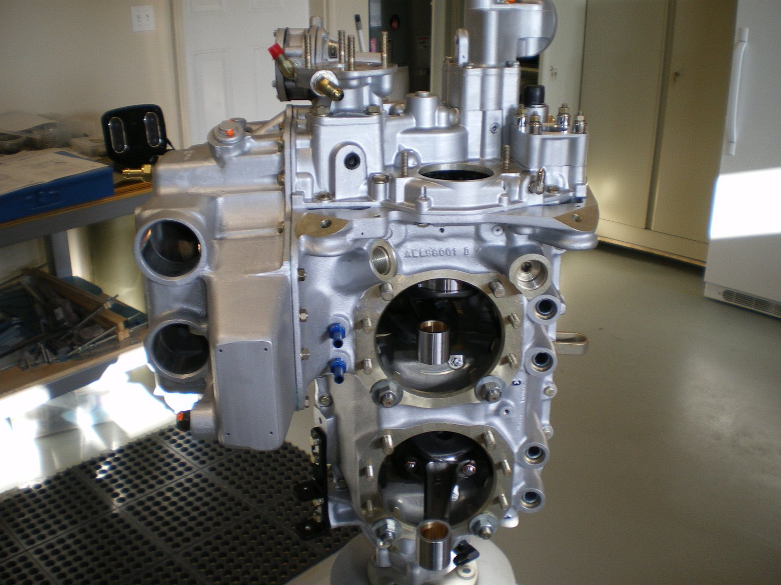
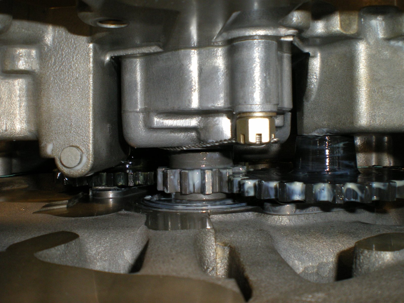
I installed the assy case. I made sure all of my timing marks were lined up, all of the nuts were safetied wired, tabs bent over on the idler shaft nuts, crankcase gear retainer in place. Fuel pump plunger is installed and lubed up. I got the gasket ready and put Locktite gasket sealer on both sides. I installed the assy case down over the tach shaft and then made sure the oil pump drive shaft lined up with the crankgear slot. I lowered it down into place and everything fit. I installed all of the 1/4 bolts that bolt it all down and torqued to 96 in/lbs. After I got this all done and started putting on the assy, I got a e-mail from a gentleman also building a ECI titan. He torqued his oil pump body nuts down to 204 in/lbs and one of his studs broke! The torque setting is more than Lycomings 150 in/lbs. It's wrong and ECI is going to get this resolved. I torqued mine a little less but over 150 in/lbs due to the holes not lining up with the castle nut. I tried combos of washers and different nuts but nothing came close. I even tried to move the stud but that was asking for disaster. I remember torquing one to 180 in/lbs to get it right and the rest were 160-170 in/lbs. This is close to the setting. The standard torque for those size and thread of bolts is 204 in/lbs. The mag studs are the same size and they are torqued to that setting. Why his stud broke is a good question. It sounds like ECI is going to take care of him and get him a new case and change the valve in the manual. I was glad to here that they took good care of him and I have always been happy with their service.
Tuesday, July 15, 2008
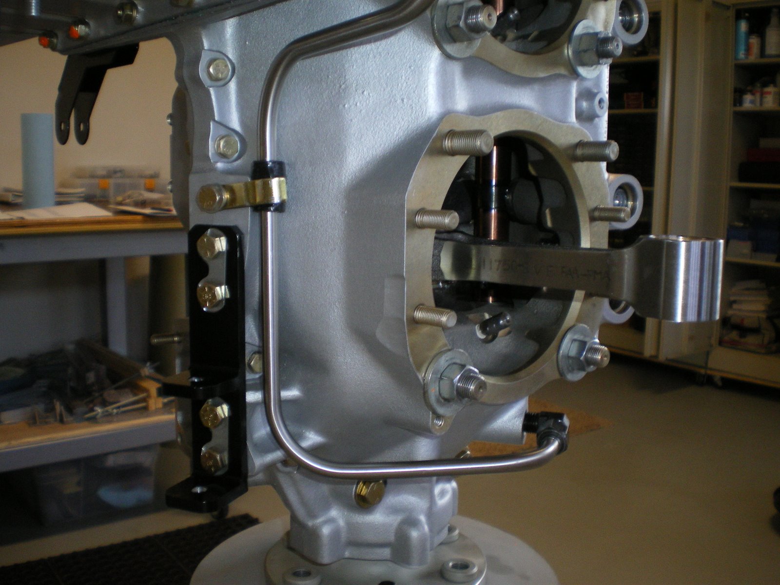
Installing the back case bolt
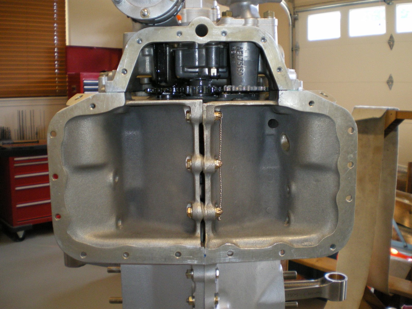
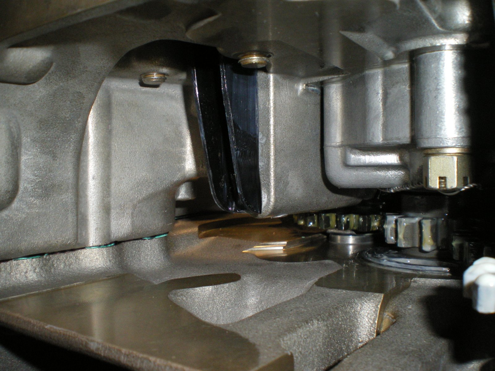
There is a case stud (3/8") that helps hold the back of the engine together. However, this bolt is under the camshaft gear. If it was not a stud, then your would have a bolt that would have had to been put in before you put the halves together just like the front main bolts. There is no orings for this since it's on the inside of the engine. Install the washer over the stud sticking out and then install the castle nut. I have a boxed eng wrench with an offset that I thinned down around the box eng. This helps it get around the nut and case. It's a tight fit in there. Get the nut tightened down and torqued and see where you hole is lined up. You can fudge a little on the torque if need be to line up the nut. Another method is to add a thin washer under the nut if needed. A thin washer was supplied in the kit but it ended up being too much and I only had abotu 3/4 of the hole visible. It says to safety wire this nut after it's torqued but we used a cotter key. It's tough to bend the tangs up but it can be done. We then safety wire the head of the cotter key over to the safety wire post next to the cam. The safety wire keeps tension of the cotter key and it also keeps the nut from rotating. This is an old trick to make it easier to get at all of that. IT'S A REAL BITCH TRYING TO SAFETY THE CASTLE NUT IN THIS TIGHT CONFINES. This other way is legal and it is flying around all over the place in the airlines. Make sure you get all of the safety wire clippings out of the assy case area and vacuum up any shavings DON'T BLOW THEM OUT.
Bottom assembly part deux
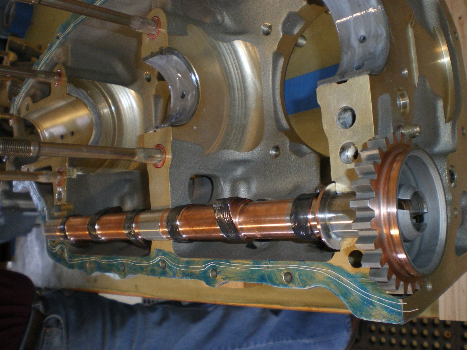
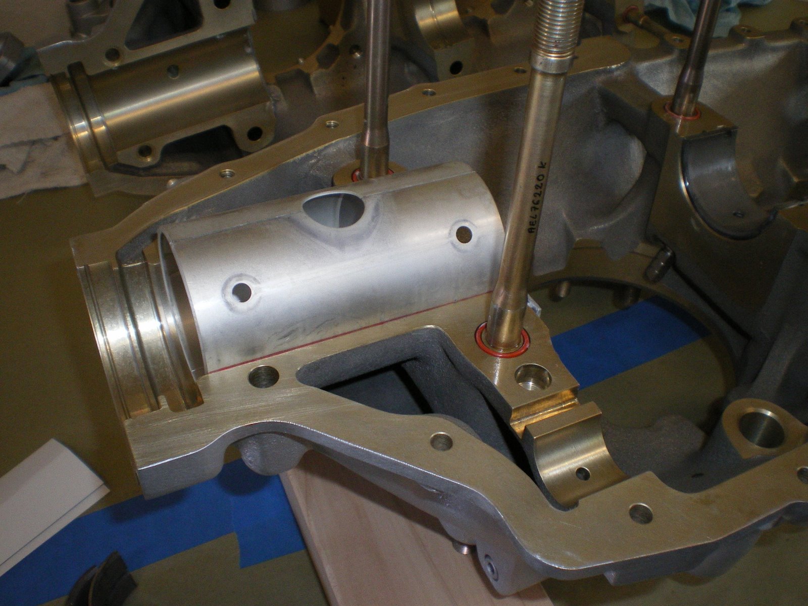
You need to take the crank shaft down off the stand and orient it so that the #1 con rod goes up and the #2 goes down. 3 will also be up and #4 will be down. The #1 con rod is the 1st one after the crank main journal area. Its the cylinder closest to the front of the engine. This is one the other person is help you hold up the con rods pointing up and the keeping them from smashing something. Set the crankshaft down into the bearings and make sure the front bearing seats in the studs and your lines you made all line back up. You know that it is down all the way if they do.
Make sure you have all of your o-rings installed around you thru bolts and your 3/8 front bolts installed with the thread pointing up. You then get the right case with camshaft and get it over the case and lower it down onto the thru bolts. You need to have your helper hold up the other con rods while you lower the case down. Set it down square to the other case using the opening of the case halves as a guide. Once its down it should come to about 3/4" from being all the way together. The cases are now riding on the thru bolt shoulders. This is a VERY tight fit and you will need to get some 1/2" nuts with big washers to use to pull the case halves together. Old cylinder bases with the top of the cylinder cut off work good to. There is a big case plate that is made for this job but it is expensive to buy. We bought grade 1/2 nuts with thick washer. We installed the on all of the thru bolts and the back cylinder studs. We deburred the washers so that no sharp edges will dig into the cylinder face on the case. Grease the bottom of the washers and nuts. They will turn and you don't want to marr the case face. Once all nuts are installed with washers slowly start turning these down. Start in the middle, then work front to back and up and down, pulliing the case halves together as square as you can. It will be tight as you are seating the case down onto the thru bolt shoulder and guide dowels. Look in your opening with a light every so often making sure nothing has fallen off the upper case like o-rings and your thrust washer. If it does, you can put them back in place carefully with a screw driver or something else. You have to be careful here as you don't want to distrub the silk thread.
Once you have pulled the case halves together and lightly tightened down the cylinder nuts, try to rotate the crankshaft and camshaft. They should mover freely and with no binding. Get the engine back up on the stand and have your helper assist you with this as this thing is not pretty heavy. Secure to the stand and get your 1/4" and 3/8" nuts ready to go along with all of the case halve bolts. DON'T TRY AND PULL OUT THE FRONT 3/8 BOLTS FOR THE FRONT MAIN BEARING FOR WHATEVER REASON, IF YOU DON AND THEN TRY TO RE-INSTALL IT, YOU WILL PINCH OFF THE O-RING PUTTING IT BACK IN AND YOUR ENGINE WILL LEAK OIL FOREVER. TRUST ME ON THIS ONE!!!!They are spelled out what size goes where and to what torque settings in the ECI hardware manual. Of course they forget to give me my castle nuts that go in the sump so I had to stop and run to the store. Install the bolts and nuts one at a time using the torque sequence lined out in the overhaul manual. Once you have go through this, install all of the rest of the bolts and torque down. Let it sit over night and come back on go through the sequence again. It'll suprise you how much the thru bolts stretch. I bet I turned them another 1/2 turn before they torqued back to 50 ft/lbs.
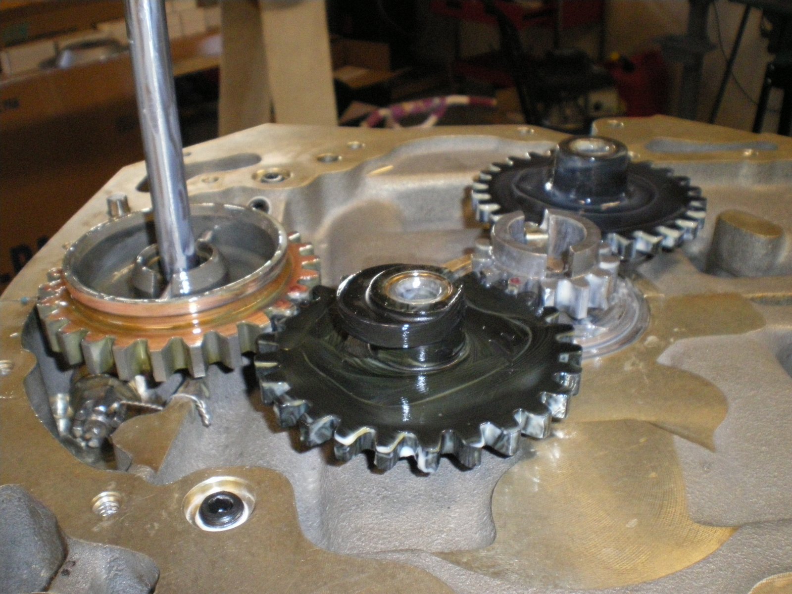
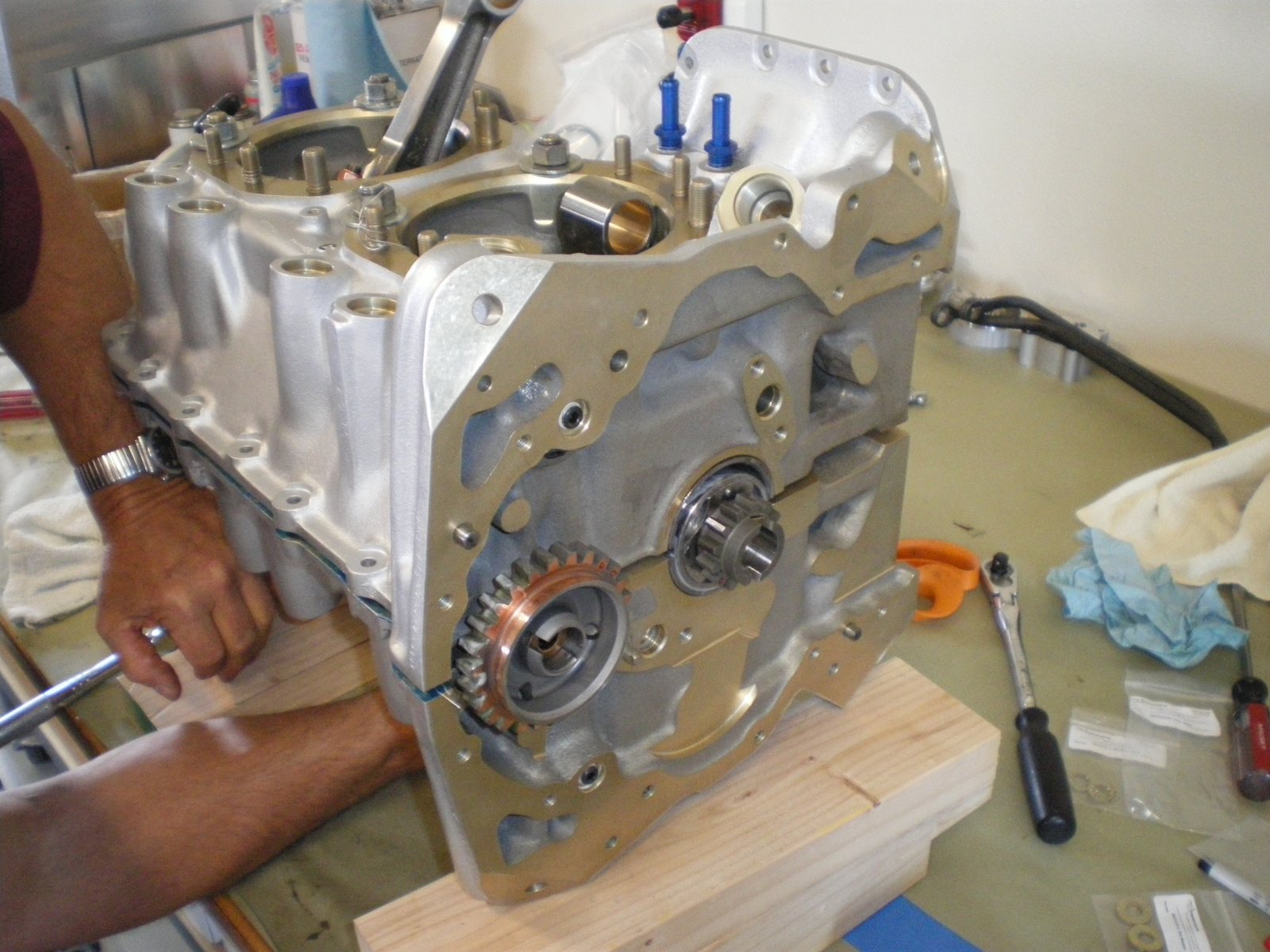
Your bottom half is done and now it's time to start installing timing gears and the assy housing.
Make sure you have all of your o-rings installed around you thru bolts and your 3/8 front bolts installed with the thread pointing up. You then get the right case with camshaft and get it over the case and lower it down onto the thru bolts. You need to have your helper hold up the other con rods while you lower the case down. Set it down square to the other case using the opening of the case halves as a guide. Once its down it should come to about 3/4" from being all the way together. The cases are now riding on the thru bolt shoulders. This is a VERY tight fit and you will need to get some 1/2" nuts with big washers to use to pull the case halves together. Old cylinder bases with the top of the cylinder cut off work good to. There is a big case plate that is made for this job but it is expensive to buy. We bought grade 1/2 nuts with thick washer. We installed the on all of the thru bolts and the back cylinder studs. We deburred the washers so that no sharp edges will dig into the cylinder face on the case. Grease the bottom of the washers and nuts. They will turn and you don't want to marr the case face. Once all nuts are installed with washers slowly start turning these down. Start in the middle, then work front to back and up and down, pulliing the case halves together as square as you can. It will be tight as you are seating the case down onto the thru bolt shoulder and guide dowels. Look in your opening with a light every so often making sure nothing has fallen off the upper case like o-rings and your thrust washer. If it does, you can put them back in place carefully with a screw driver or something else. You have to be careful here as you don't want to distrub the silk thread.
Once you have pulled the case halves together and lightly tightened down the cylinder nuts, try to rotate the crankshaft and camshaft. They should mover freely and with no binding. Get the engine back up on the stand and have your helper assist you with this as this thing is not pretty heavy. Secure to the stand and get your 1/4" and 3/8" nuts ready to go along with all of the case halve bolts. DON'T TRY AND PULL OUT THE FRONT 3/8 BOLTS FOR THE FRONT MAIN BEARING FOR WHATEVER REASON, IF YOU DON AND THEN TRY TO RE-INSTALL IT, YOU WILL PINCH OFF THE O-RING PUTTING IT BACK IN AND YOUR ENGINE WILL LEAK OIL FOREVER. TRUST ME ON THIS ONE!!!!They are spelled out what size goes where and to what torque settings in the ECI hardware manual. Of course they forget to give me my castle nuts that go in the sump so I had to stop and run to the store. Install the bolts and nuts one at a time using the torque sequence lined out in the overhaul manual. Once you have go through this, install all of the rest of the bolts and torque down. Let it sit over night and come back on go through the sequence again. It'll suprise you how much the thru bolts stretch. I bet I turned them another 1/2 turn before they torqued back to 50 ft/lbs.
Your bottom half is done and now it's time to start installing timing gears and the assy housing.
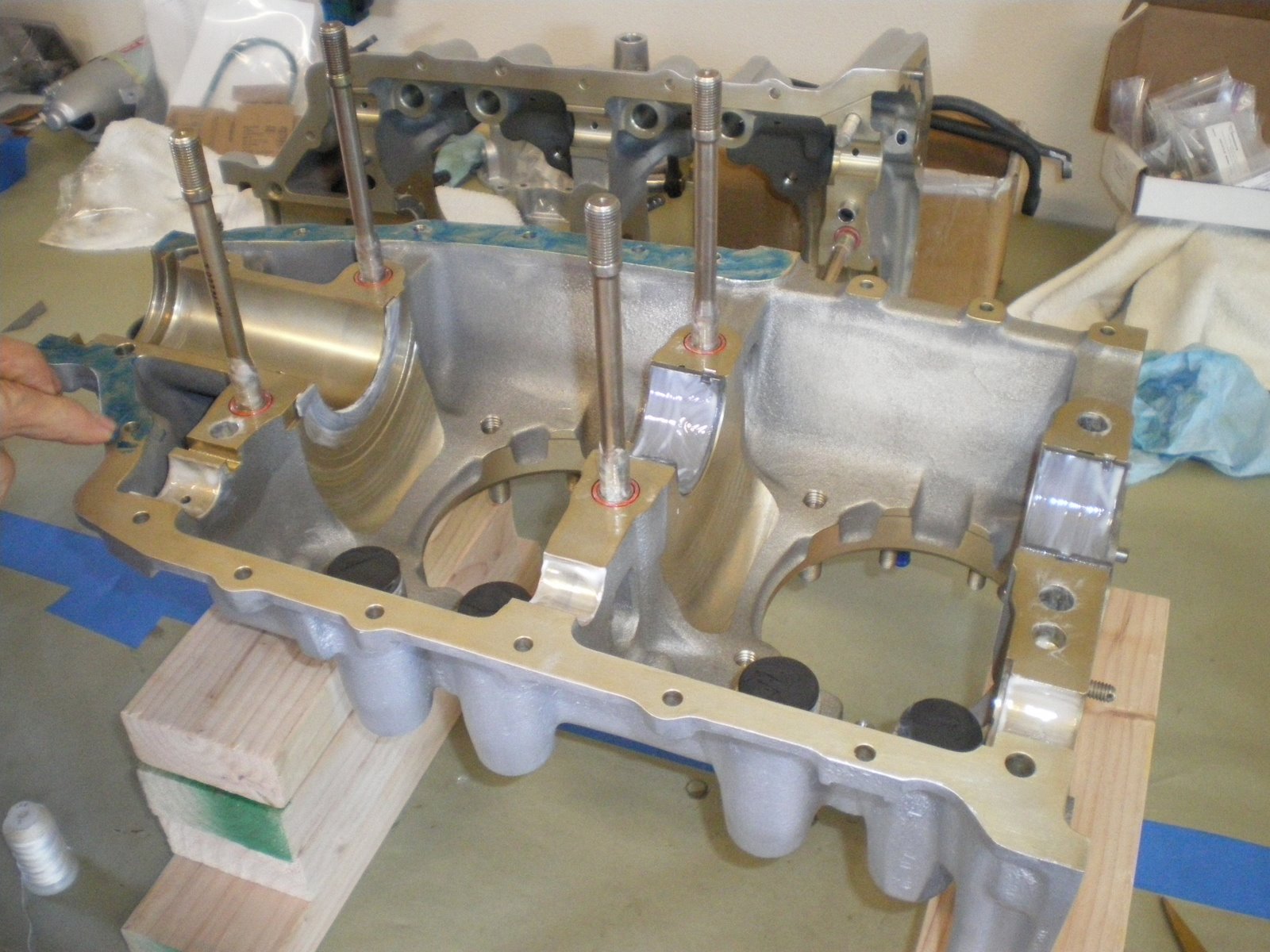
Bottom engine assembly
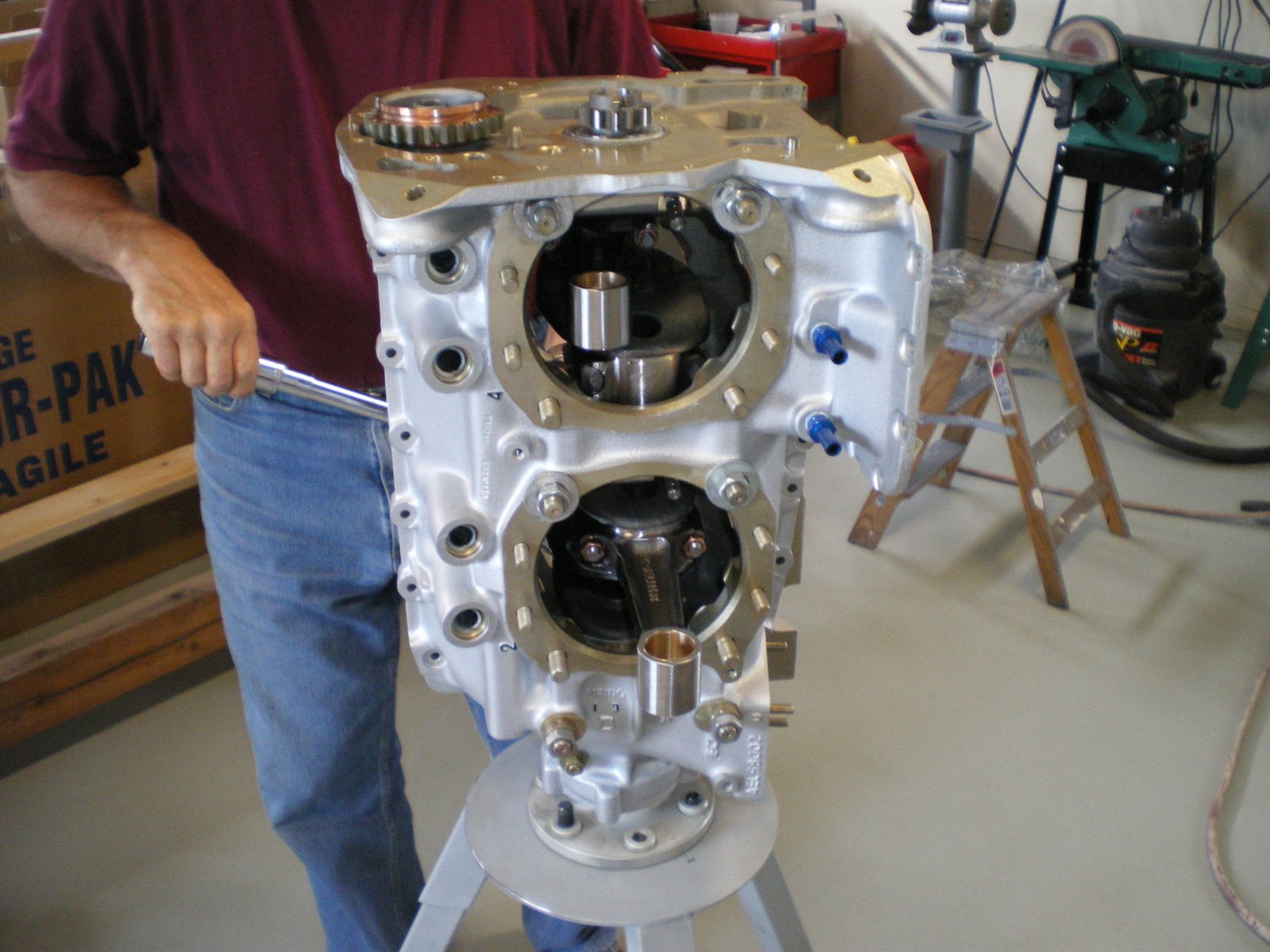
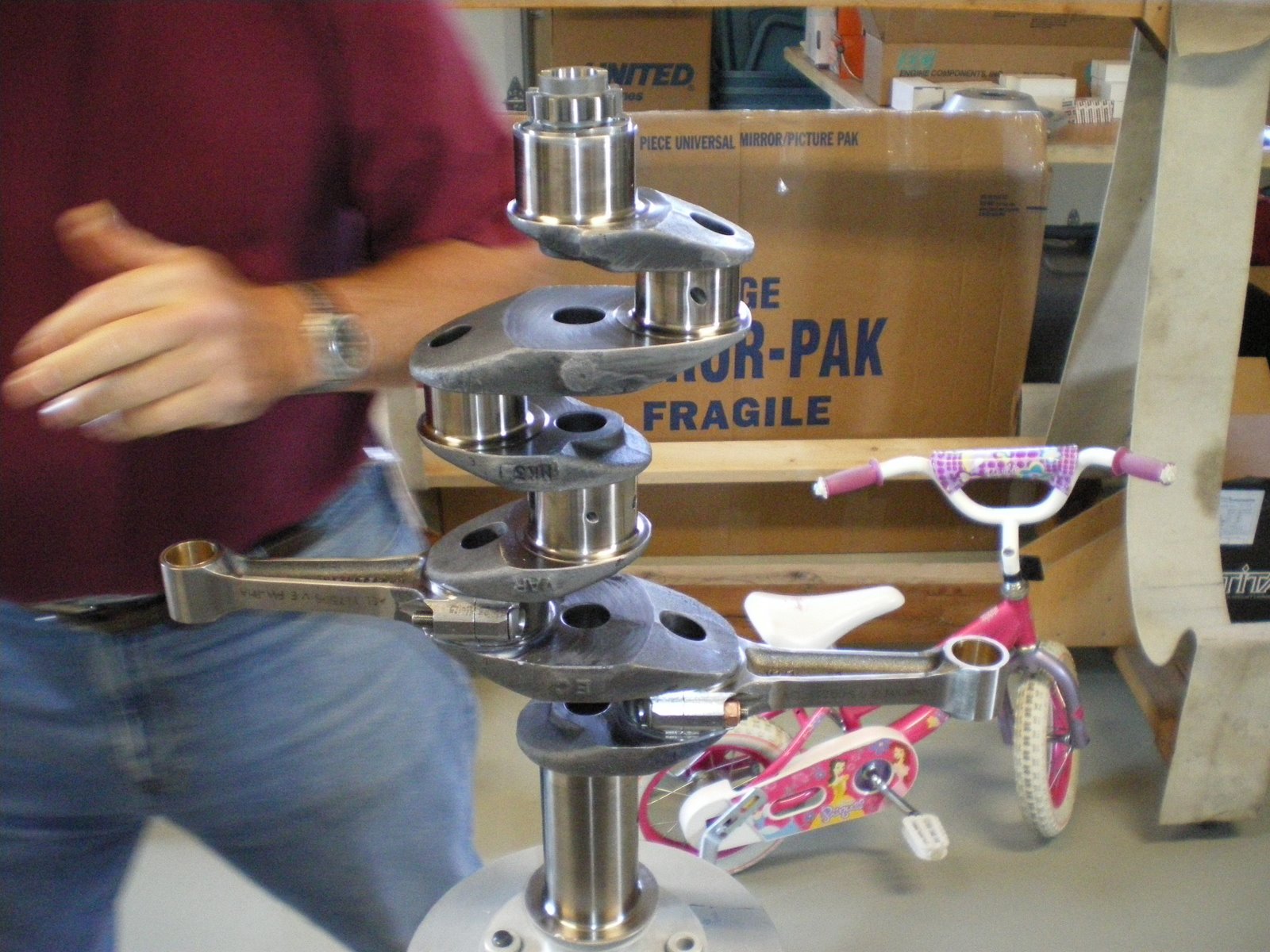
I put the bottom half together yesterday. My Dad flew up in his Harmon Rocket to help me out. It takes two people to man handle the crank and crankcase onto the engine stand and table.
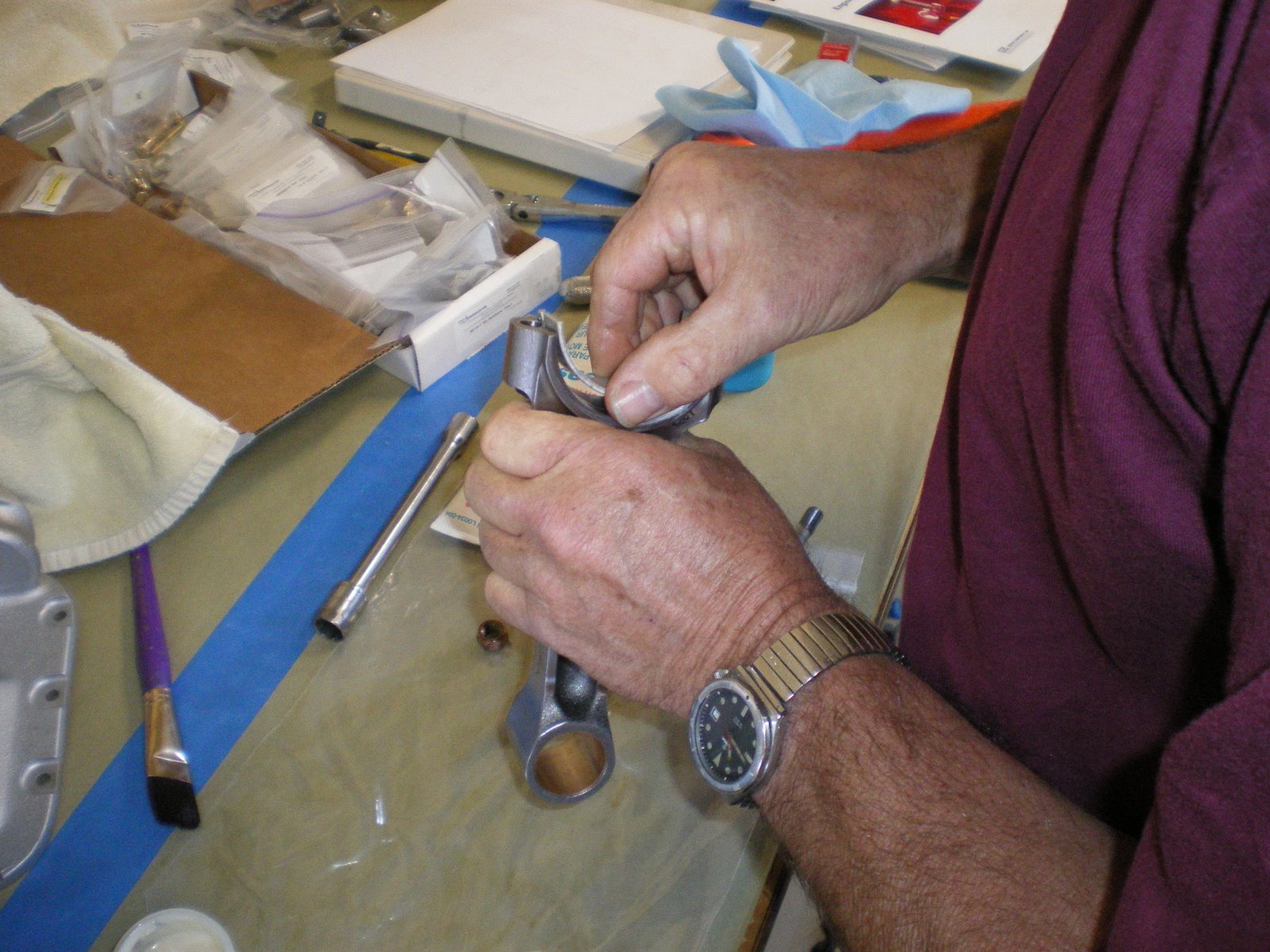
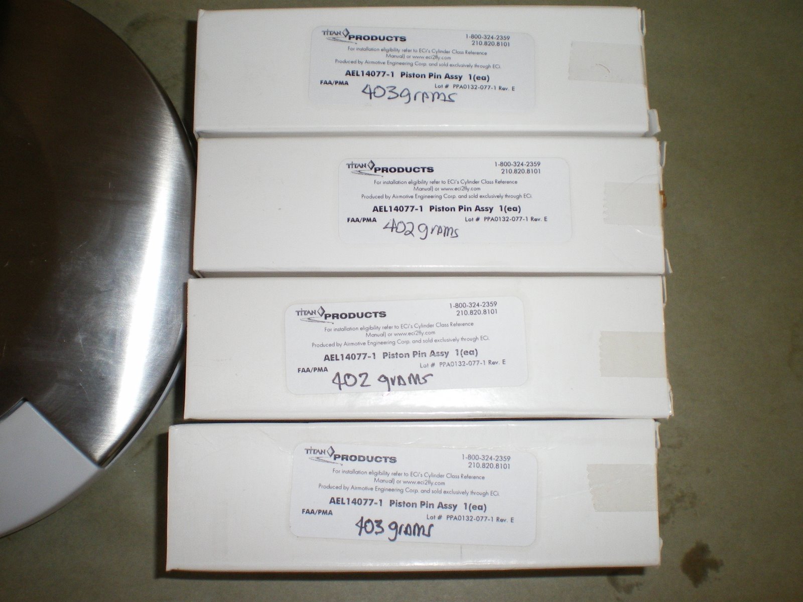
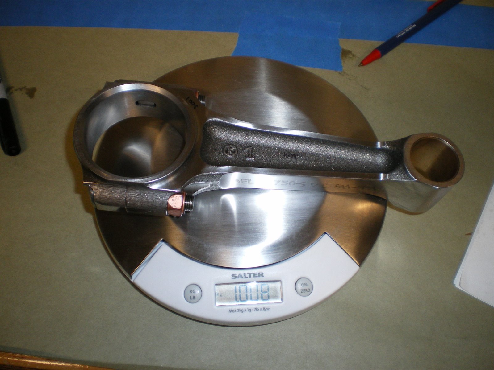
I started out by weighing the connecting rods. I had two that weighed 1007 grams and two at 1005 grams. Since I had two of each I opposed the two heavies and the two lite weight ones. This means that each side has the same amount of weight on it. I then weighed the pistons, they all weighed 1264 grams. The piston pins were weighed. Two were 402 grams and two were 403. I did the same as the con rods and opposed them. When I go to install the cylinders, I will have to keep track of all of this so I don't mess it up. When it's all done I should only be out of balance by one gram, but since they are opposed from one another it cancels the other side out. Hopefully this will result in a very smooth engine.
Next I got the bench all cleaned off and covered with masking paper. This will help keep thing clean. You don't want any dust getting down into your engine when it's on the bench.
I then got all of the parts cataloged and cleaned up ready for install. The parts come coated with cosmoline and it all has to be wiped down with a solvent to get it off. I set the crank shaft up on the engine stand and then started getting the connecting rods ready. I blew out all of the crackshaft oil galleries with air before I started installing rods. I put a thin film of oil behind the con rod bearings and then seated the bearings down into the rods. Since this is all new parts, there shouldn;t be a need to measure all of these partrs for clearances. If this was an overhauled engine I would be checking the bearings and con rods for proper fit onto the crack journals. Plastigauge works well for this.
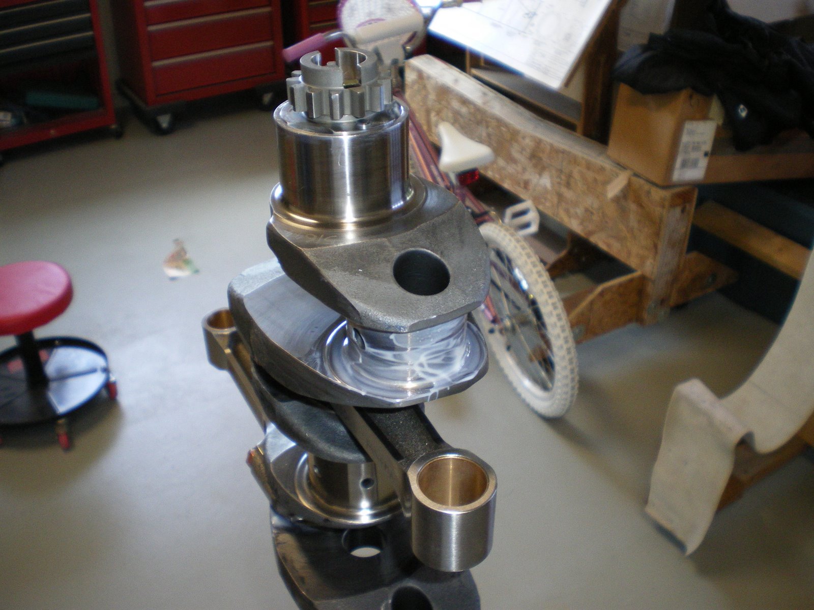
After all of the con rods have bearings installed in them, I started mouting them onto the crankshaft. I kept track of the weights and I also installed them so all of the numbers on the rods point down. When I say down I mean the numbers will always be looking at the oil pans. These keeps the rods oriented all the same way. I can't say for sure but I don't think this matters but It's how the overhauled manual says it needs to be done.
I put a lot of the elephant snot on the bearings and journals before I put them together. I installed all of the con rods on the crank before I torqued them all down. They get torqued to 480 in/lbs. I triple checked these bolts as you don't want them coming off. The nuts to the con rod bolts go with the shoulder pointing out. There have been cases where these nuts got put on backwards and there is not enough surface area to spread the torque around and they dug into the top half of the con rod and started to fail.
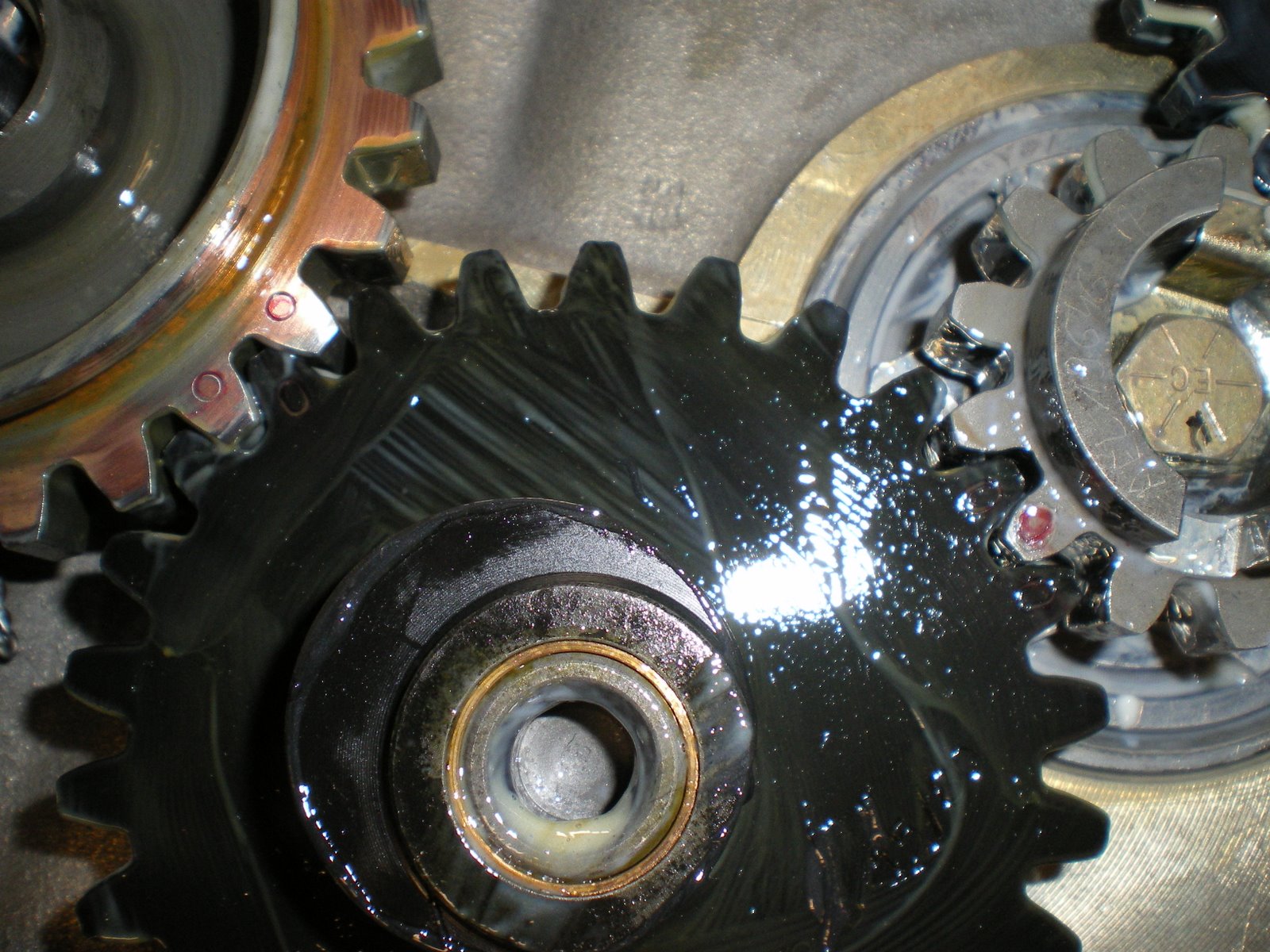
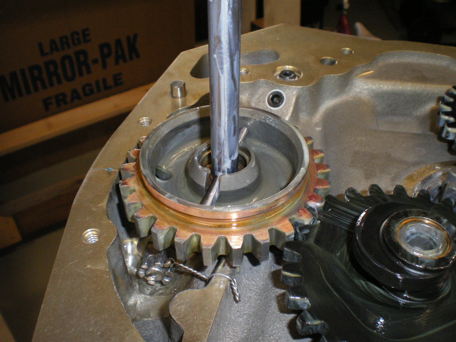
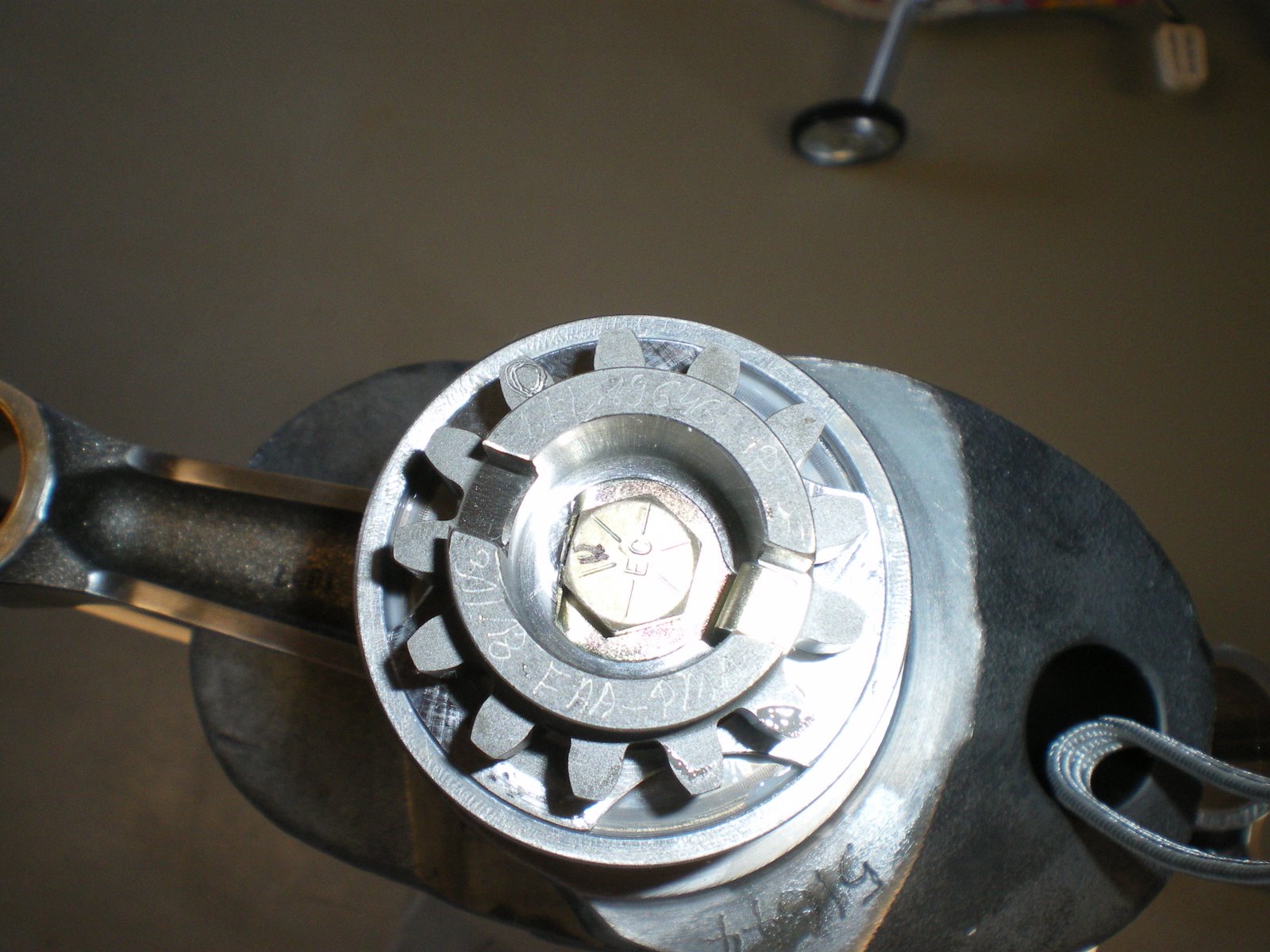
After they are all torqued, I intalled the crank gear on the back of the engine. You can't screw this up because it has a hole drilled in the gear to orient it on the crankshaft. A small film of oil go underneath the gear and I put a very light film on the threads of the crankgear bolt. I out the retainer plate down and torque the bolt down to 204 in/lbs. I mark the flat side of the bolt head to the back side of the retainer plate. I then take all apart and slightly bend up the retainer plate so that it easier to get at when you go to bend the tab up for final install. Put the retainer plate back down into the slot and install the bolt, torque to 204 in/lbs. Bend the tab up with a screwdriver and tap the tab up against side of the bolt head. This locks this into place. Be careful not to scratch the crank gear when you are trying to bend this tab up. Take your time.
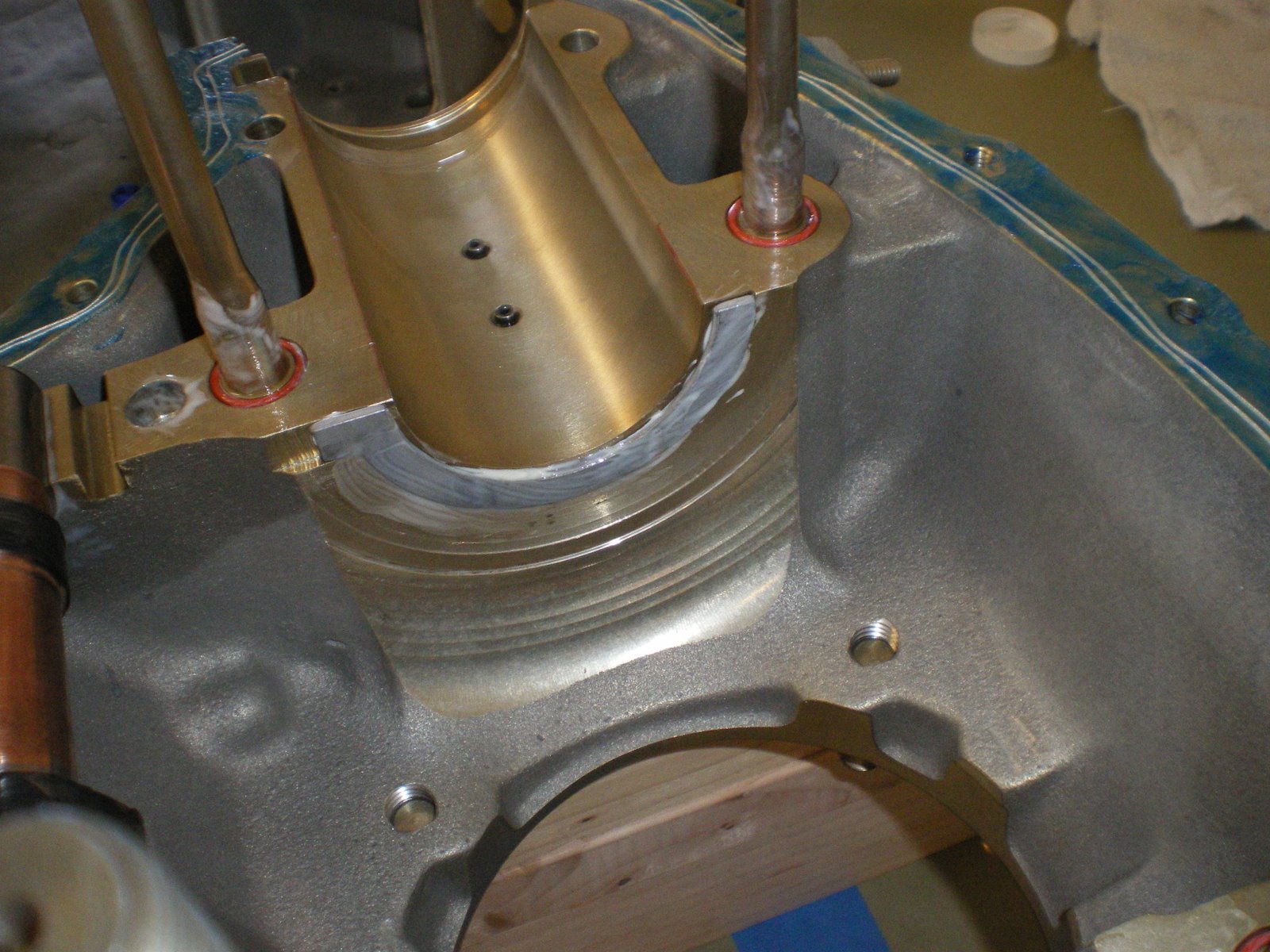
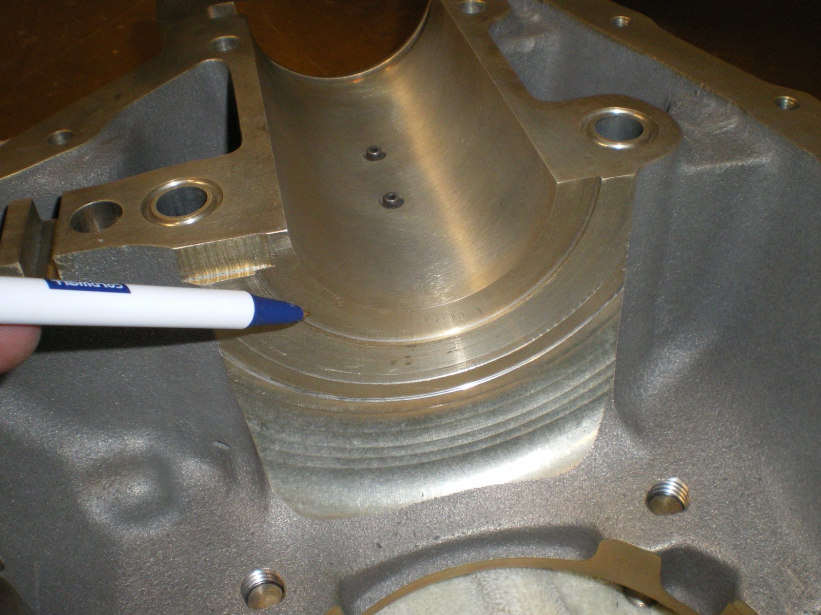
Next is to lay the case halves up on the bench. Lay the left half down and block it up with three 2X4's on each end. This gives up clearance for the con rods when you lower it down into place for assembly. I started putting all of the bearings into place. I slightly oiled behind each bearing and then installed. Lightly tapping into place with a small RUBBER hammer. Don't use a metal hammer to tap these into place. It will mar the bearing surface and put scratches into your crank journals. Installed the full of front main bearings into the right half of the case. There is two little studs that place the bearing. Once it's down into place, take a very sharp pencil or sharpie and mark the case half line onto the bearing. Take it out and lube it all up and install it on the CRANKSHAFT, get the orientation of this right. When you lower the assembly into the case the holes for the studs will go down. THis gives you a reference line to use when you are dropping the crank down into the case so it will lay down onto those studs. All of the studs keep the bearing from spinning with the crank.
Once I installed all of the bearings, I installed the tappets. I lubed them up with snot and also the hole they go into. Don't forget to lube the inside of the tappet as well. Be careful there, you want a film not a blob. You plungers will go in there and you don't want to get oil in them yet until you have done your valve clearances. Put the tappets in the other case half as well. Get your moly-lube and put on the face of the tappets. Do they same for the lobes of the camshaft as well. Don't put this stuff on the camshaft journals this will sit in the case. The snot is for the journals. Put the camshaft in the right side and take some .025 safety wire and loop it around the camshaft and then out the piston holes and wire it to one of the cylinder hold down studs. This will secure the camshaft and tappets into place while you are lowering down the case half onto the case half laying on the bench.
My engine had the thrust bearing option. This is great but it turned out to be a real PITA to install. We use snot to keep it held up against the front of the crankcase behind the main bearing. This didn't work out well when we were lowering the upper case half down onto the lower. If you use this option, get some very sticky axle gear. Not sythetic either. IT NEEDS TO BE REAL AXLE GREASE. This will hold it in place. You can only put these on one way and the tab on the end has a slot for on the case for it to go.
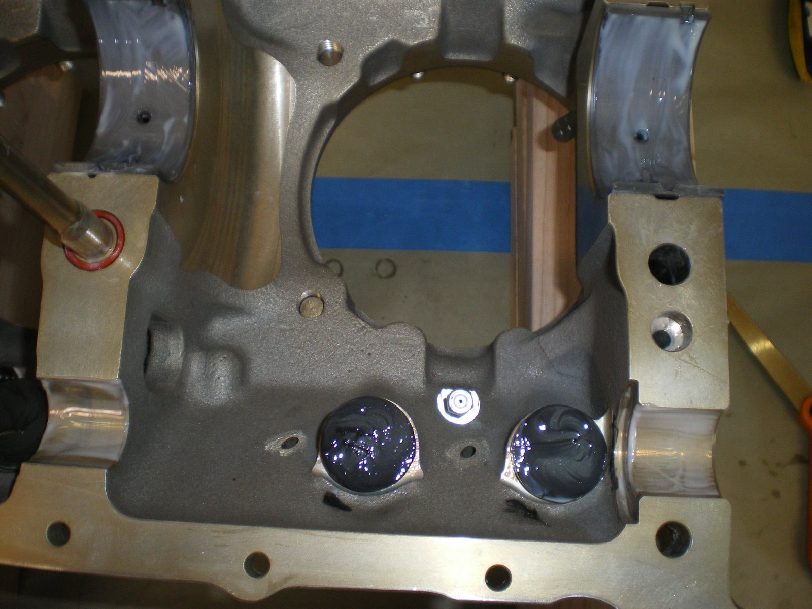
Next is to install the silk thread and hylomar on the faces of the case halves. Spread a thin film of hylomar onto the left case half. It only goes on the outter faces, not down where the oil pan is and does not go on any internal faces. Put a VERY THN FILM on the other half as well. Next is to install TWO lines of silk thread. Keep the thread on the INSIDE of the bolts holes. I have seen some that got around the outside and if the oil gets by on thread it will just come out the bolt hole-not good and usually is very messy. There are several areas that there is not much room for the thread to lay on the inside of the bolt so pay attention here. Extend the thread to run out the ends of the case faces in the back/bottom and into the front of the case where the front seal goes. You will trim the excess off the back. Leave only about 1/8" of extra string hanging out in the front main seal area.
After the string is done, install all of the thru bolt orings that go around the thru bolts and recess groves around them in the case halves. THere are three kinds. One for the middle four bolts, one for the back two bolts, and one set for the front 3/8" bolts on the front main bearing. This is the time to also install the front two 3/8" bolts with washer. Lift the case up and out them on the so the threads stick up into the air. Lube all o-rings before installing them onto the thru bolts so they slide down easier. Once the front bolts are in place and all o-rings are in place. Triple check your parts. All bearings installed, silk thread and hylomar, o-rings, camshaft, tappets, thrust washer, cooling nozzles... Basically all of the parts that you can't install with the case halves together. Your ready to take the crank off the stand and lower it down into the left case half.
I started out by weighing the connecting rods. I had two that weighed 1007 grams and two at 1005 grams. Since I had two of each I opposed the two heavies and the two lite weight ones. This means that each side has the same amount of weight on it. I then weighed the pistons, they all weighed 1264 grams. The piston pins were weighed. Two were 402 grams and two were 403. I did the same as the con rods and opposed them. When I go to install the cylinders, I will have to keep track of all of this so I don't mess it up. When it's all done I should only be out of balance by one gram, but since they are opposed from one another it cancels the other side out. Hopefully this will result in a very smooth engine.
Next I got the bench all cleaned off and covered with masking paper. This will help keep thing clean. You don't want any dust getting down into your engine when it's on the bench.
I then got all of the parts cataloged and cleaned up ready for install. The parts come coated with cosmoline and it all has to be wiped down with a solvent to get it off. I set the crank shaft up on the engine stand and then started getting the connecting rods ready. I blew out all of the crackshaft oil galleries with air before I started installing rods. I put a thin film of oil behind the con rod bearings and then seated the bearings down into the rods. Since this is all new parts, there shouldn;t be a need to measure all of these partrs for clearances. If this was an overhauled engine I would be checking the bearings and con rods for proper fit onto the crack journals. Plastigauge works well for this.
After all of the con rods have bearings installed in them, I started mouting them onto the crankshaft. I kept track of the weights and I also installed them so all of the numbers on the rods point down. When I say down I mean the numbers will always be looking at the oil pans. These keeps the rods oriented all the same way. I can't say for sure but I don't think this matters but It's how the overhauled manual says it needs to be done.
I put a lot of the elephant snot on the bearings and journals before I put them together. I installed all of the con rods on the crank before I torqued them all down. They get torqued to 480 in/lbs. I triple checked these bolts as you don't want them coming off. The nuts to the con rod bolts go with the shoulder pointing out. There have been cases where these nuts got put on backwards and there is not enough surface area to spread the torque around and they dug into the top half of the con rod and started to fail.
After they are all torqued, I intalled the crank gear on the back of the engine. You can't screw this up because it has a hole drilled in the gear to orient it on the crankshaft. A small film of oil go underneath the gear and I put a very light film on the threads of the crankgear bolt. I out the retainer plate down and torque the bolt down to 204 in/lbs. I mark the flat side of the bolt head to the back side of the retainer plate. I then take all apart and slightly bend up the retainer plate so that it easier to get at when you go to bend the tab up for final install. Put the retainer plate back down into the slot and install the bolt, torque to 204 in/lbs. Bend the tab up with a screwdriver and tap the tab up against side of the bolt head. This locks this into place. Be careful not to scratch the crank gear when you are trying to bend this tab up. Take your time.
Next is to lay the case halves up on the bench. Lay the left half down and block it up with three 2X4's on each end. This gives up clearance for the con rods when you lower it down into place for assembly. I started putting all of the bearings into place. I slightly oiled behind each bearing and then installed. Lightly tapping into place with a small RUBBER hammer. Don't use a metal hammer to tap these into place. It will mar the bearing surface and put scratches into your crank journals. Installed the full of front main bearings into the right half of the case. There is two little studs that place the bearing. Once it's down into place, take a very sharp pencil or sharpie and mark the case half line onto the bearing. Take it out and lube it all up and install it on the CRANKSHAFT, get the orientation of this right. When you lower the assembly into the case the holes for the studs will go down. THis gives you a reference line to use when you are dropping the crank down into the case so it will lay down onto those studs. All of the studs keep the bearing from spinning with the crank.
Once I installed all of the bearings, I installed the tappets. I lubed them up with snot and also the hole they go into. Don't forget to lube the inside of the tappet as well. Be careful there, you want a film not a blob. You plungers will go in there and you don't want to get oil in them yet until you have done your valve clearances. Put the tappets in the other case half as well. Get your moly-lube and put on the face of the tappets. Do they same for the lobes of the camshaft as well. Don't put this stuff on the camshaft journals this will sit in the case. The snot is for the journals. Put the camshaft in the right side and take some .025 safety wire and loop it around the camshaft and then out the piston holes and wire it to one of the cylinder hold down studs. This will secure the camshaft and tappets into place while you are lowering down the case half onto the case half laying on the bench.
My engine had the thrust bearing option. This is great but it turned out to be a real PITA to install. We use snot to keep it held up against the front of the crankcase behind the main bearing. This didn't work out well when we were lowering the upper case half down onto the lower. If you use this option, get some very sticky axle gear. Not sythetic either. IT NEEDS TO BE REAL AXLE GREASE. This will hold it in place. You can only put these on one way and the tab on the end has a slot for on the case for it to go.
Next is to install the silk thread and hylomar on the faces of the case halves. Spread a thin film of hylomar onto the left case half. It only goes on the outter faces, not down where the oil pan is and does not go on any internal faces. Put a VERY THN FILM on the other half as well. Next is to install TWO lines of silk thread. Keep the thread on the INSIDE of the bolts holes. I have seen some that got around the outside and if the oil gets by on thread it will just come out the bolt hole-not good and usually is very messy. There are several areas that there is not much room for the thread to lay on the inside of the bolt so pay attention here. Extend the thread to run out the ends of the case faces in the back/bottom and into the front of the case where the front seal goes. You will trim the excess off the back. Leave only about 1/8" of extra string hanging out in the front main seal area.
After the string is done, install all of the thru bolt orings that go around the thru bolts and recess groves around them in the case halves. THere are three kinds. One for the middle four bolts, one for the back two bolts, and one set for the front 3/8" bolts on the front main bearing. This is the time to also install the front two 3/8" bolts with washer. Lift the case up and out them on the so the threads stick up into the air. Lube all o-rings before installing them onto the thru bolts so they slide down easier. Once the front bolts are in place and all o-rings are in place. Triple check your parts. All bearings installed, silk thread and hylomar, o-rings, camshaft, tappets, thrust washer, cooling nozzles... Basically all of the parts that you can't install with the case halves together. Your ready to take the crank off the stand and lower it down into the left case half.
Saturday, July 12, 2008
Hang tite!
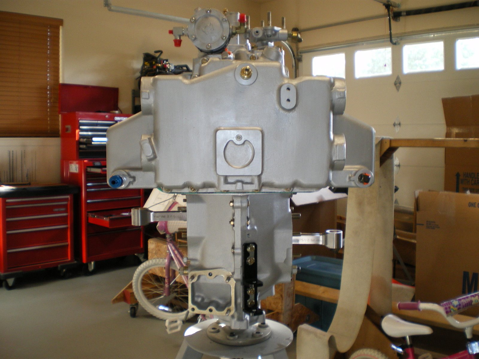
I will be posting again soon. I have been painting the engine. I didn't want to bore you with this task. However, I will say this, I use a GOOD engine enamel. I selected POR-15 painted from SpaceAgefinishes.com. A pint was about 25 buck. I bought two pints of silver and one pint of gloss black. I have hand painted all of the parts with TWO coats of paint. One coat is OK, but two will fill in the sand cast finish a little and make the engine a little more glossy. I paint with a camel hair brush. I did thin down the enamel to spray the cylinder heads. It's a lot of masking to do the cylinder in both silver and black. The other reason for hand painting is I can get a good coat in all of those little areas that are hard to reach with a spray gun. I have taken the time to paint some of the assy as well. The fuel pump and governor got a coat as well as all of the assy pads.
Now some will ask why I have not used a good poly-urethane paint like PPG concept or Chroma-One. I don't want to do all of that masking for one. I don't want to have the issues of spraying in my garage and my family in the house. I do not want to get any of that paint inside the engine and if I did, it would take a lot of work to get it out.
I also spoke with the guru's at several paint shops. They were not thrilled about the heat ratings of the PPG concept on the engine. You could paint the case parts all one color and leave cylinders bare and you would be OK but then the engine would look dorky. Aerosports paints their engines with Concept and they are doing OK, but it's not the recommended paint. That's why the high temp enamels are around. This paint will hold up to 700 degree temps. More than enough for my engine temps. They will also hold up to solvents and oils one the engine has ran and "baked" the paint a little. I will be posting pics of the crankshaft build here on Monday. See ya soon.
Tuesday, July 1, 2008
It's been a few days
I have been slowing working on the engine. Mostly getting ready for painting. I have cataloged some parts and installed all of the 1/8 pipe plugs in the case and assy case. I have installed the oil pump and put a 1/8 fitting on the bottom of the sump for a sniffle valve to let fuel out when the engine stops.
Thursday, June 26, 2008
Pics of the engine.
Took several pictures of the piston cooling nozzles. I installed them using high temp thread sealant. I also installed the 1/8 pipe plugs for the galleries after I blew out all of the lines.
Wednesday, June 25, 2008
Getting Ready
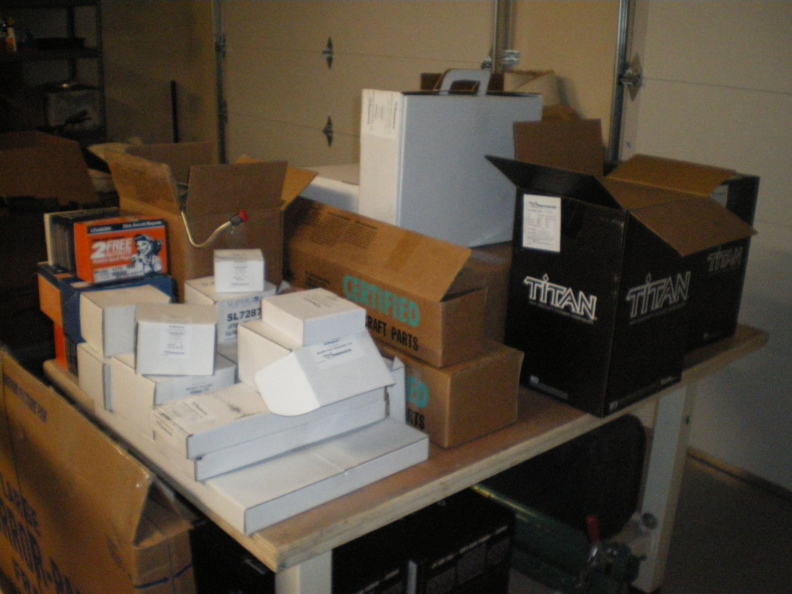
Today I started getting organized to begin the engine building process.
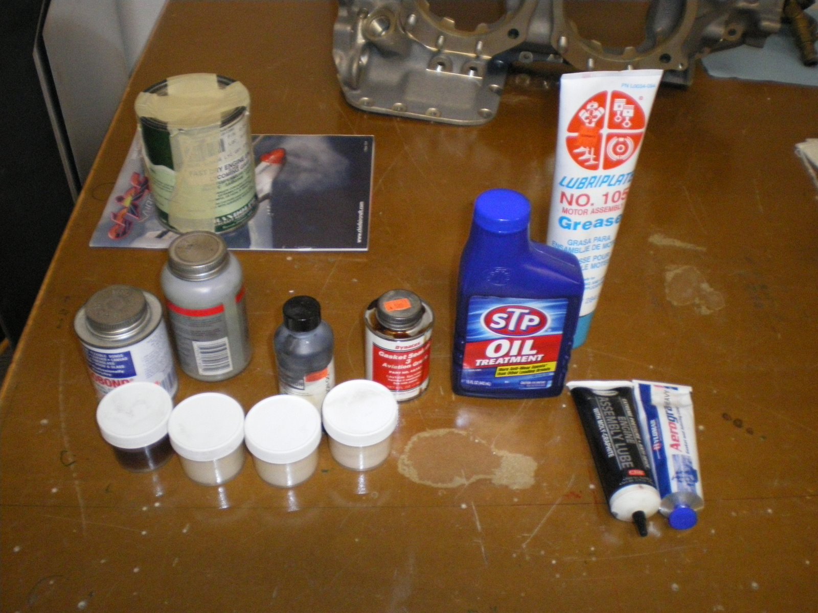
I gathered a few items (consumables) like 50W oil(mineral), Moly assembly lube (for camshaft), STP and lubriplate. I mix these two at a 50/50 mix in a small jar. This is my ASSEMBLY LUBE, called elephant snot: it will go on all the bearings, gear teeth, and wear surfaces around the engine so that when it's started up, there will be no damage to the engine. It will also protect the parts during storage. I also have silk thread (oo) for the case halves, aero grade hylomar (for the case halves), aero gasket maker (non-hardening), fuel lube (for bolt/pipe thread lubricant) and a anti-seize lubricant.
I bought my engine enamel from Spaceagepaints.com. I am going with POR-15 high temp engine enamel. It will withstand 700 degrees. The case, assy case, jugs, and sump will all be painted aluminum/silver and the jug bases will be painted gloss black in the same stuff. I HAND PAINT all of my parts with a camel hair brush-two coats. This paint is supposed to have more solids and less solvents. It also has a high gloss and is resistant to chemicals when it is dry. I could have gone with PPG concept, but they really don't recommend that at the paint shop since the max temps for it are 300 degrees. Plus I would have to mask off all of the parts so no over spray gets into the inner parts. I also have two daughters running around the house and I don't need to gas them out with fumes from isocyanates. I will paint all of the parts and take pics later.
Here are some things we need to do the right way from the beginning.
DOCUMENT ALL PARTS!!!!!!
Aerosport provided me with a list of the parts, however if there is a assembly package-like the crankcases and thru-bolts, it does not break this down. I will expand on this list and write down ALL of the part #'s used and any LOT/BATCH or SERIAL #'s. I will have a written copy for the engine book and a excel spreadsheet of it for storage. This is very anal retentive but if there is ever a recall, you know what you have for parts and can do a trace very easily. When Lycoming has a recall on their crankshaft, it only took me 5 minutes to find out if I was going to have to disassemble my engine or not.
Get a good engine stand to build your engine on.
A big table top is great for having everything at your disposal.
Get two-CERTIFIED torque wrenchs. I have one Snap-On in a 1/4" drive in/lbs and one Husky 3/8 drive ft/lbs. The Husky is not certified but my Dad works for a regional airline as a mechanic
and he took this one into work and checked it out on their torque gauges and it was spot on at all check points. So this basically makes it certified. But having a torque wrench that is spot on is a must have when putting together a aircraft engine. There are several no-no's when when using a torque wrench. Never leave the wrench torqued up over long periods of time. This will damage the spring in there and then it will not be accurate. After each session with the wrench, unload it all the way back to zero. If you do leave it by chance, go get it checked out again. There is also a technique to torquing a nut. Don't creep up on it. Turn like you would normally do until the wrench clicks. When torquing case bolts and cylinder hold down bolts, pay close attention to the sequence.
I have a lot of tools to build this engine. I don't have them all-(do you ever) but I have enough to do almost everything. Some of the ones you need the most is the deep sockets and extensions. I also have a set of wobble socket in 1/4" drive. This really helps getting in some of those tight places. Like beind the camshaft gear at the very back of the engine. Some other ones is a set of good safety wire pliers. You will also need some allen drives in 5/16, 1/4, 3/16, 5/32 (if your not using the piston cooling nozzles). Get some feeler gauges, a razor blade, a pair of sharpe dykes, a good set of screw drivers, some small pry bars, a couple of 3/16 punches (to fold over the lock plates). You will need some .032 safety wire.
I also have an assortment of GRADE 8 nuts and bolts-course thread. This kit comes with all of the hardware-we will see. I always get some extra internal lock washers just in case.
There are some specialty tools like cylinder base bolt wreches that I will have to borrow. I will most likely take my cylinders to someone and have them put them together. You need a ring compressor and a special press to press the valve springs down with. We have used a drill press before with a bracket but you run the risk of scraping the valve stem if this is not done right. I will of course make sure this process is captured. You also need a special pry bar to get the front crank seal over the crankshaft flange. If you use a screw driver, you can slip and put scratches in the crankshaft-NOT GOOD.
Today I started on prepping the crank case. I took out all of the pipe plugs from the oil galleries and cleaned all of the threads. I am going to use both piston cooling and camshaft lubrication nozzles on this engine so I am making damn sure there is not any grit in any of the galleries to plug my nozzles. I use compressed air to blast out the passages. I also take a soft tipped air hose and blast out all of the bearing oil passages. I have blown out sand and grit from these passages before after overhauling and getting cases shaved down. It could clog up your oil flow if you don't. THen that means bearing failures and another overhaul.
YOU WANT TO MAKE SURE YOU PUT ALL OF THESE PIPE PLUGS BACK IN THE CASE WHEN YOU ARE DONE. IF YOU LEAVE THE ONES OUT IN THE REAR ASSY HOUSING YOU HAVE TO TAKE IT ALL APART TO PUT THEM BACK IN.
I will be using the 8 ports on the inside of the case that are machined for the cooling nozzles.
I also cleaned all of the cooling/lubrication nozzles with some solvent and checked the small ball valve that is inside of them. The are pressure controlled and won't let on squirt onto the piston or cam until about 50psi is reach. You carefully insert a small wire (.032 SS) into them and compress the spring. I then blew them out. Several were very sticky from the preservative oil that was in them.
Tomorrow I will post some pics of the engine and start installing the cooling nozzles.
Subscribe to:
Posts (Atom)


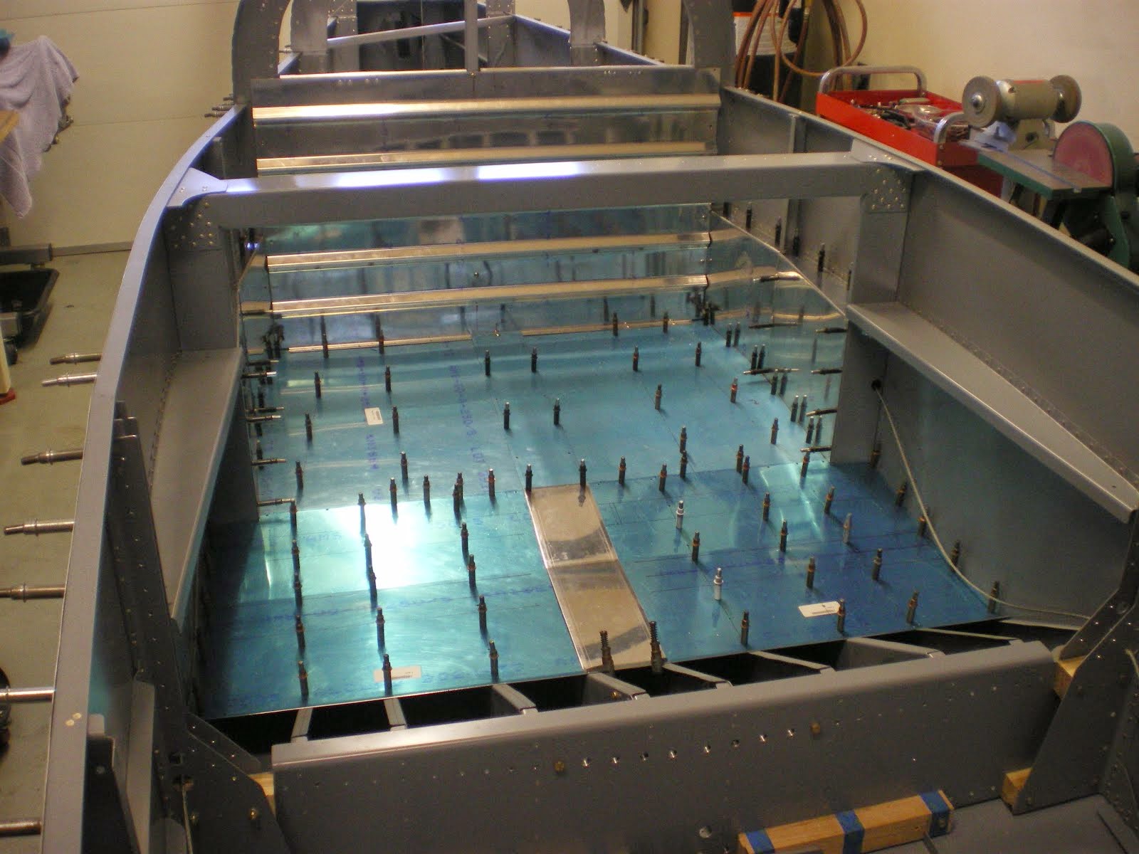


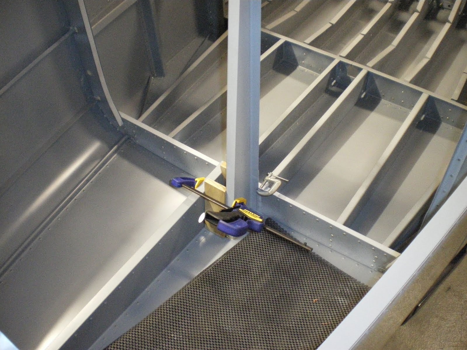


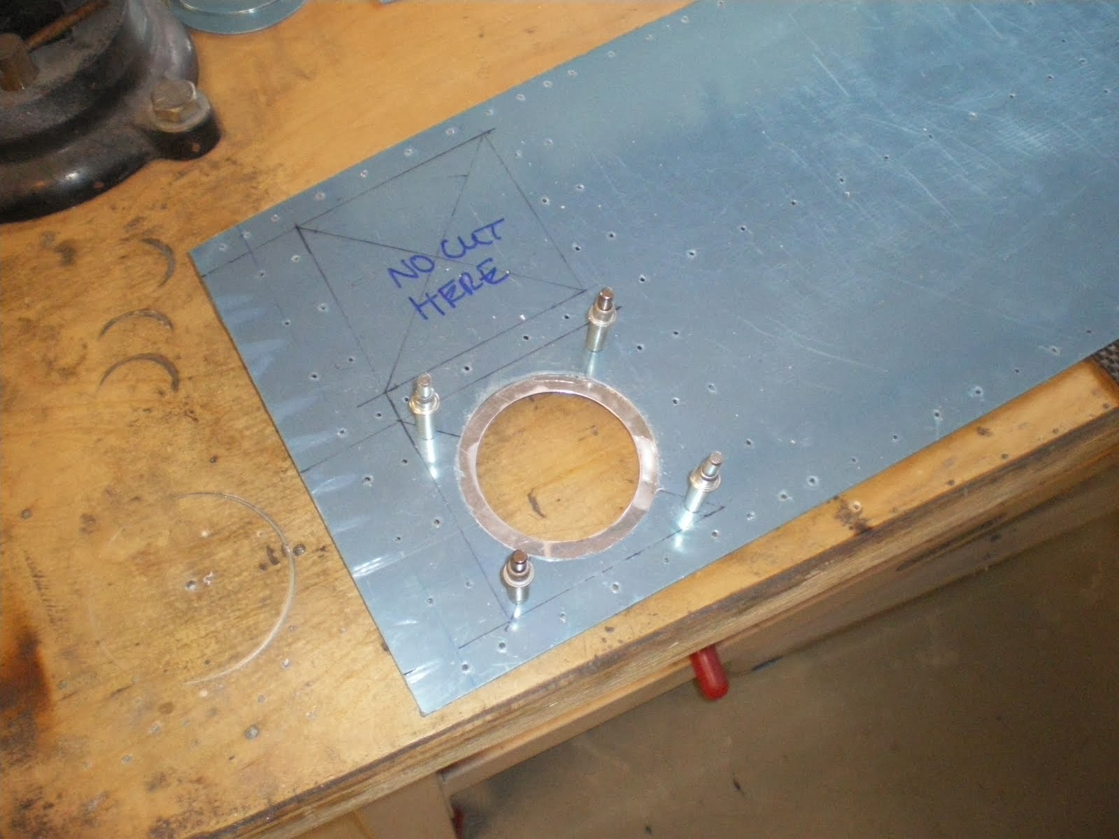


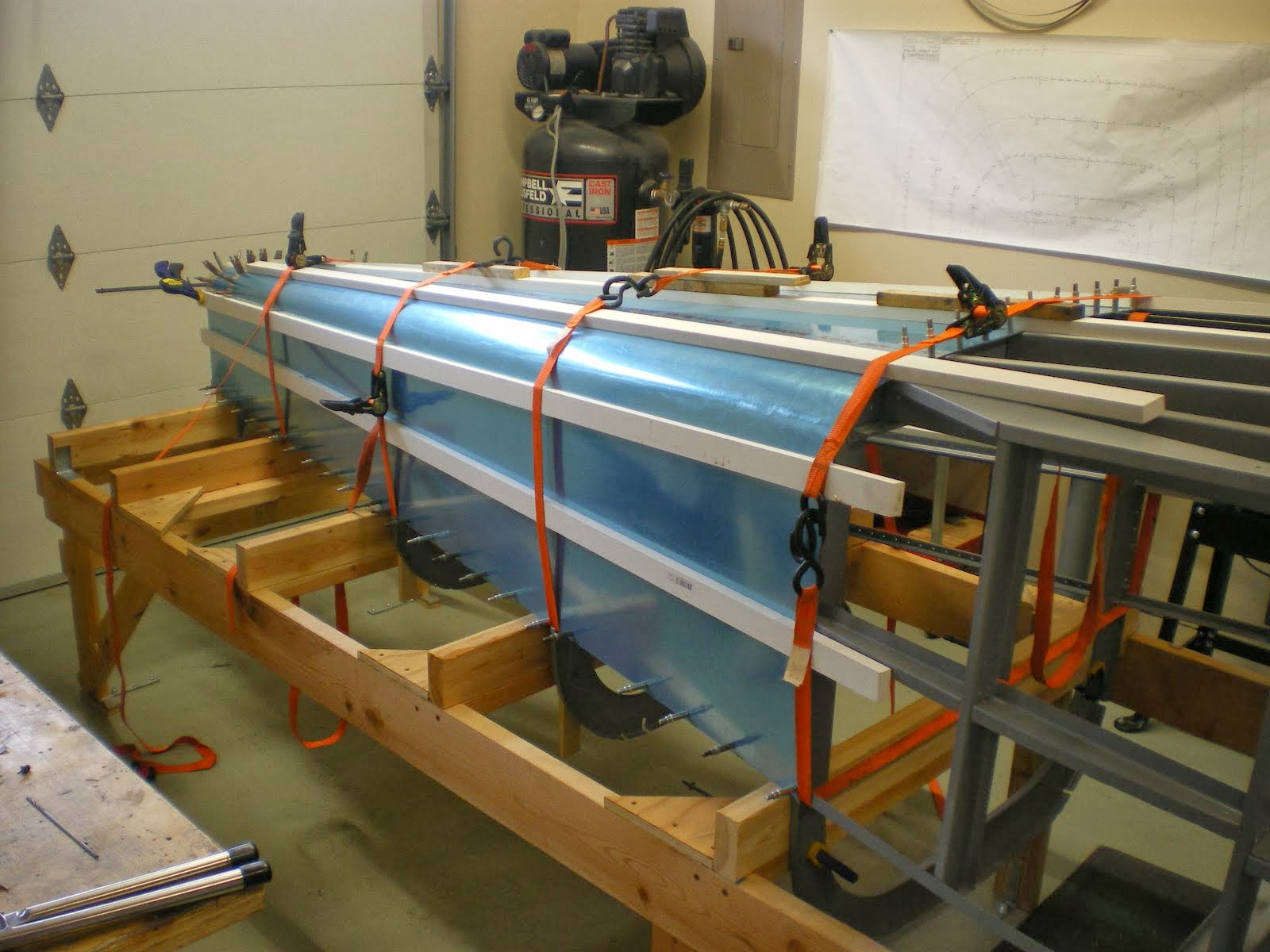


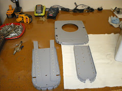


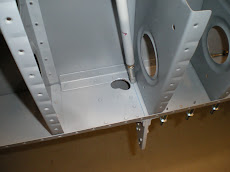


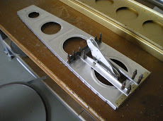


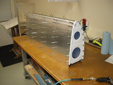

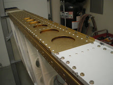


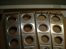
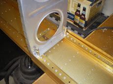
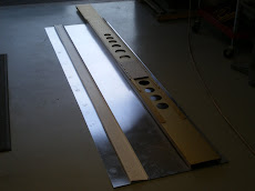
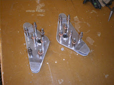
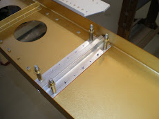
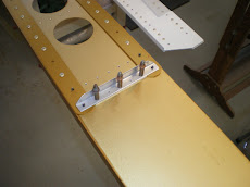
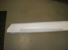
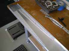
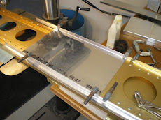
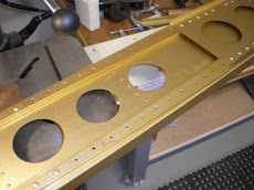
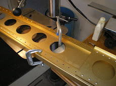


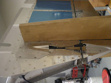
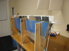
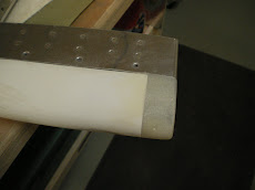
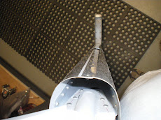
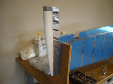
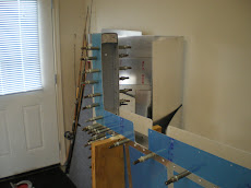
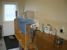
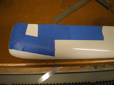
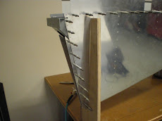
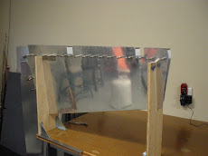
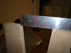
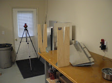
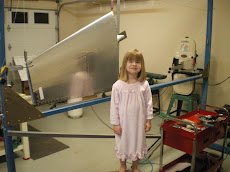
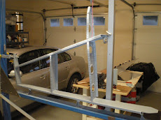
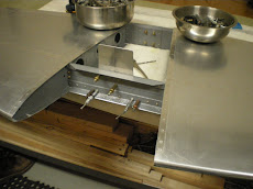
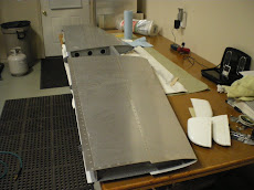

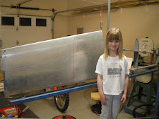
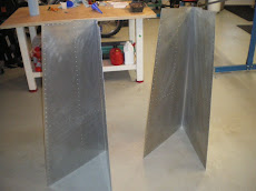
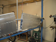


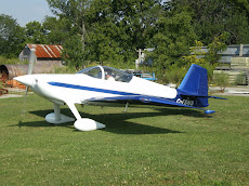
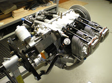
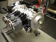
.JPG)