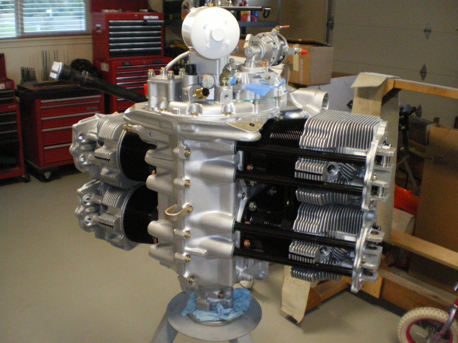
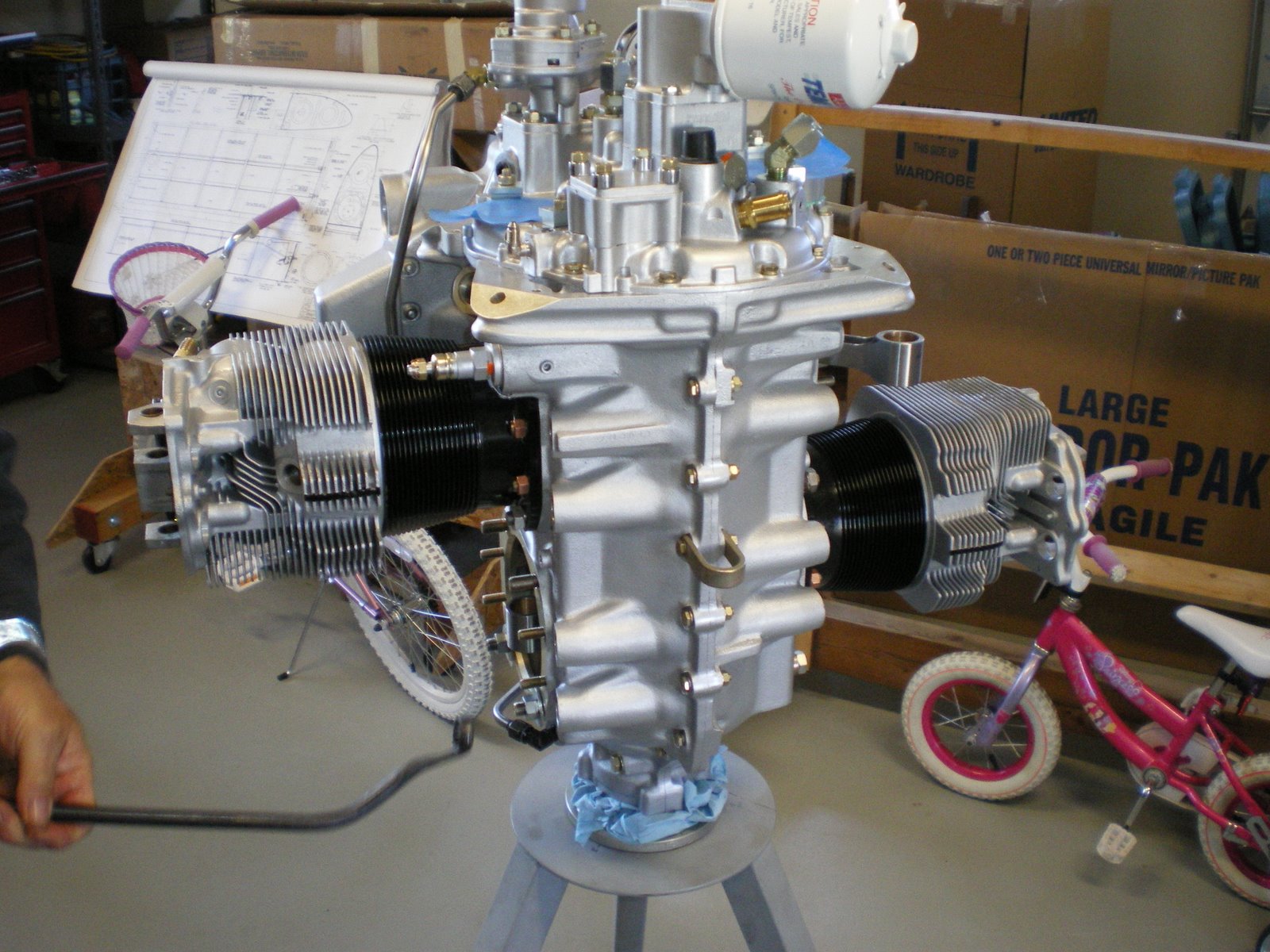
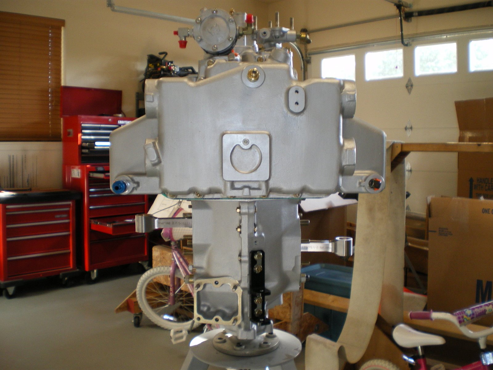
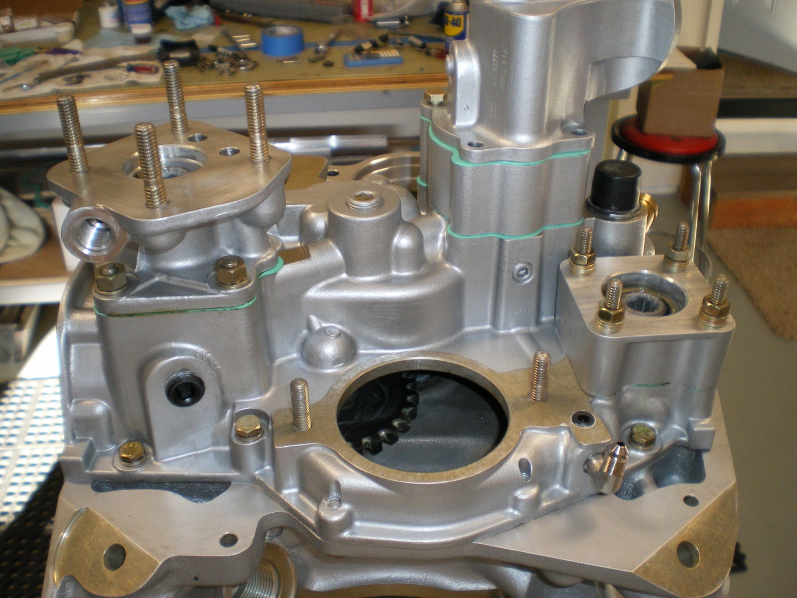
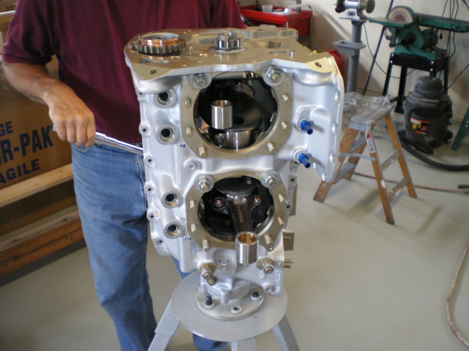
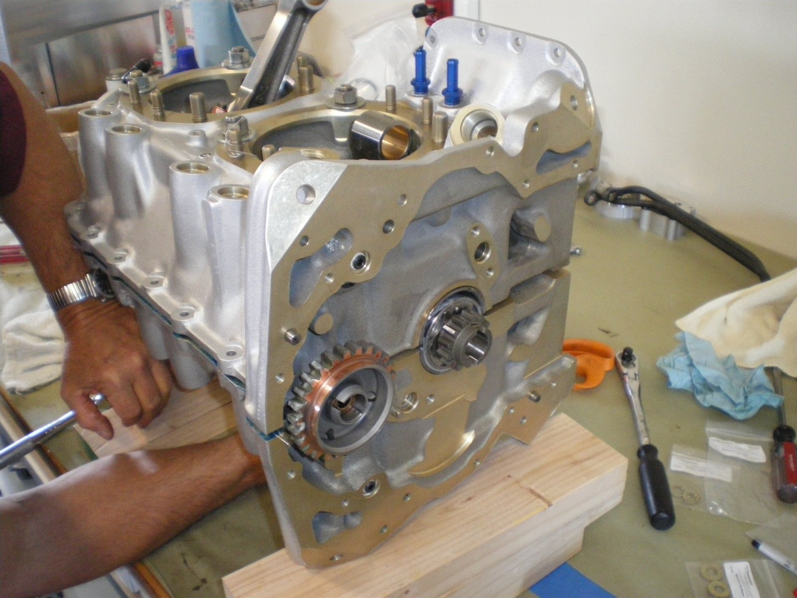
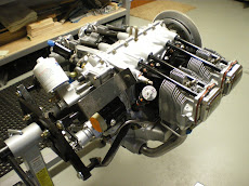
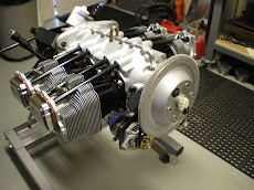
I have been working on the engine but I have also been on vacation. I have gotten the engine off the stand now and mounted to the horz stand that I can rotate it on. I have installed the rocker arm covers and spark plugs. Next is to mount the starter and alternator.
The starter is pretty straight forward. Just mount it and put on the four nuts, washer and lockwasher and torque it all down to 17ft/lbs.
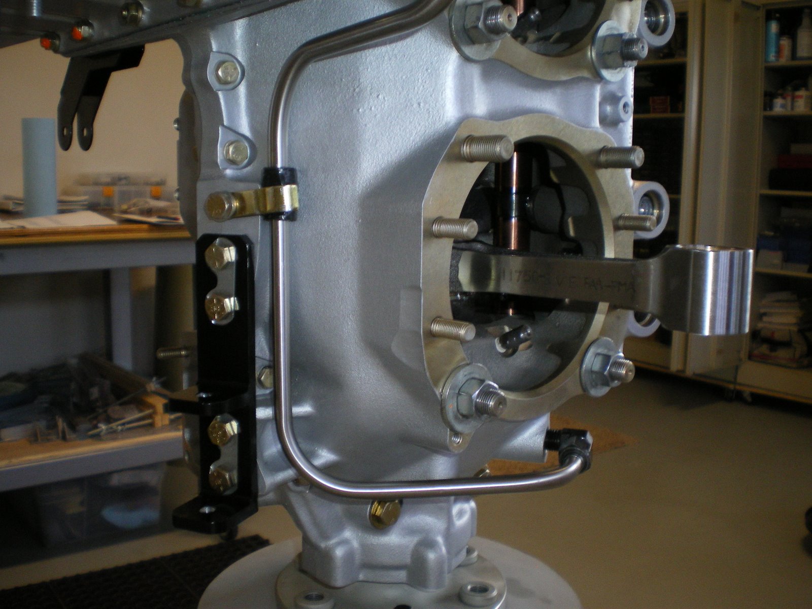
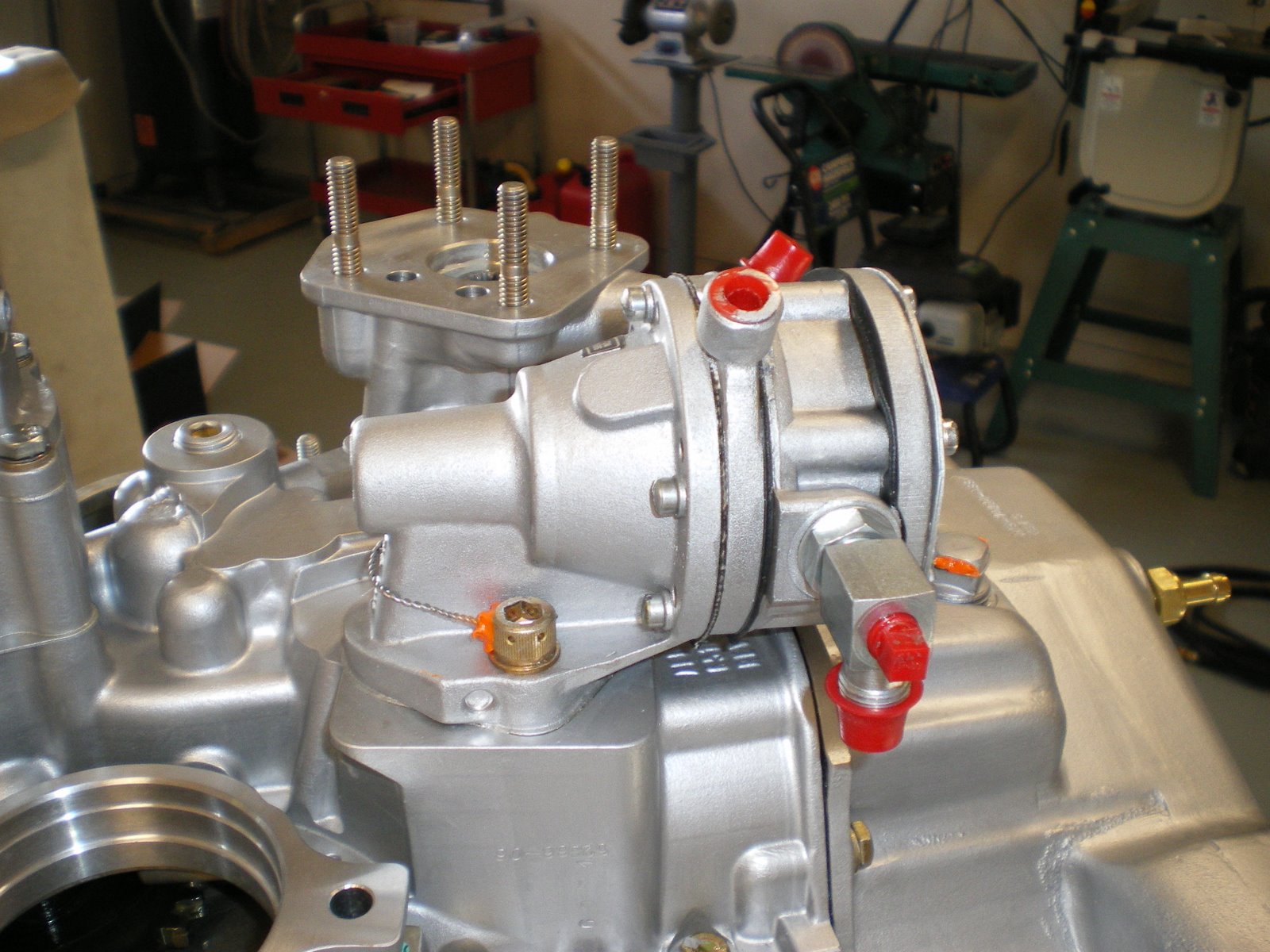
The alternator is a different story. I already has the mounting brackets painted black. On my last engine I used the 40 amp alt. This engine will have the 60 amp alt. It has an internal volt regulator. It is smaller and more compact but there are other issues with it. You have to mess with the mounting a lot more to get it to fit. I bolted it up there on the brackets already bolted to the engine case. I saw right off that I was not in line with the ring gear. I was forward on the alt about 3/16 of an inch. I was able to use washers on the last alt to move it back and forth to get the line up. I cannot do that on this one. I get out the directions(typical male-mount first, read directions later) and find out that I have to slot the mounting bracket to move it aft. I had to take it off, sand blast it, have someone at work help me slot the holes, repaint it and remount it. That took about 3 days when it was all said and done back on the engine. I then had to mount the alt and get the alignment of the two pulleys and then torque it all down. Next comes the alt arm and cross brace to the starter. The alt arm I had to bend up to fit right and then you have to fab up a cross brace from the alt to the starter. This helpe brace the starter during a kick back.
You have to get the distance between the holes perfect to get it all to line up and fit. Once that was all done, I got out the right mag and timed it with the timing pin. Just rotate and drop the pin into the left rotation hole until it fall all the way in. Put #1 cyl on the compression strok at 25 degree BTDC and then insert mag. PUt on the retaining mounts and tighten it all down. I won't torque it all down until I get both mags on and time together. I still have to pull the spring on my impulse mag and turn it around. It came off and I mounted it back on in reverse. Go figure, I had a 50/50 chance of getting it right.
Wednesday, August 27, 2008
Saturday, August 23, 2008
Pushrods and Rocket covers
I have installed all of the pushrods on the engine. Aerosport has gotten me all of the -35 length pushrods I need. For some reason, all of the intake pushrods needed to be -35's and the exhaust one were -34's. That put all but one in the mid range of .050 clearance between the valve stem and rocker arm. I had one intake that was .035 clearance which is with in tolerance but that doesn't leave too much room since the min clearance is .028.
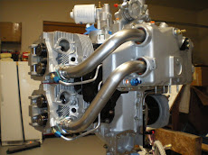
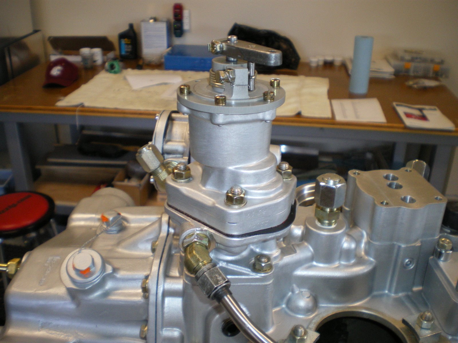
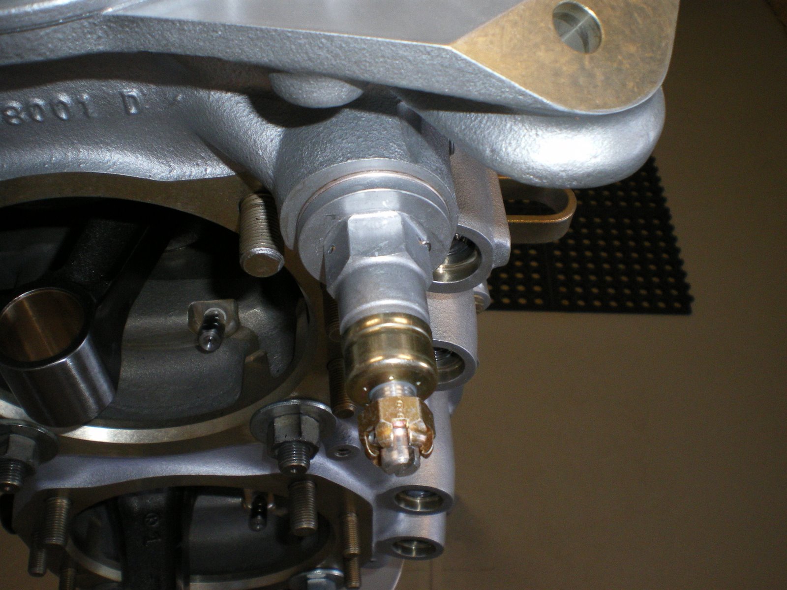
I purhcases some silicon rocker cover gaskets from Van's. I threw the cork gaskets away. They are leakers over time and you will back to installing silicon one. Pay atttention to the torque specs on the rocker cover screws with silicon gaskets. These are reusable gaskets. Covers are on and I have also installed the prop governor oil line. The clip they give you to hold the line down unders the cylinders is a little tight and pulls the line over too much. Looking through my pile of adel clamps, I found a longer one and installed it. It now is not in a bind at all. This will cut down on the stress of the line.
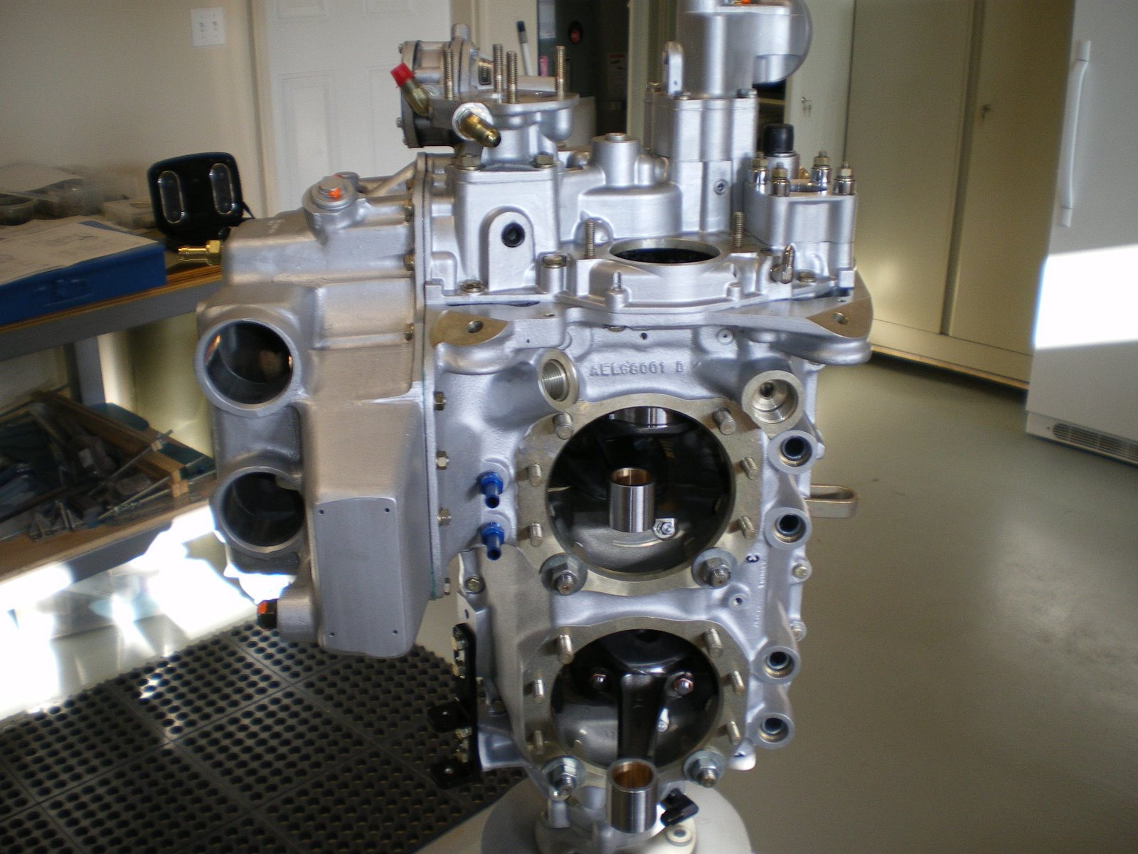
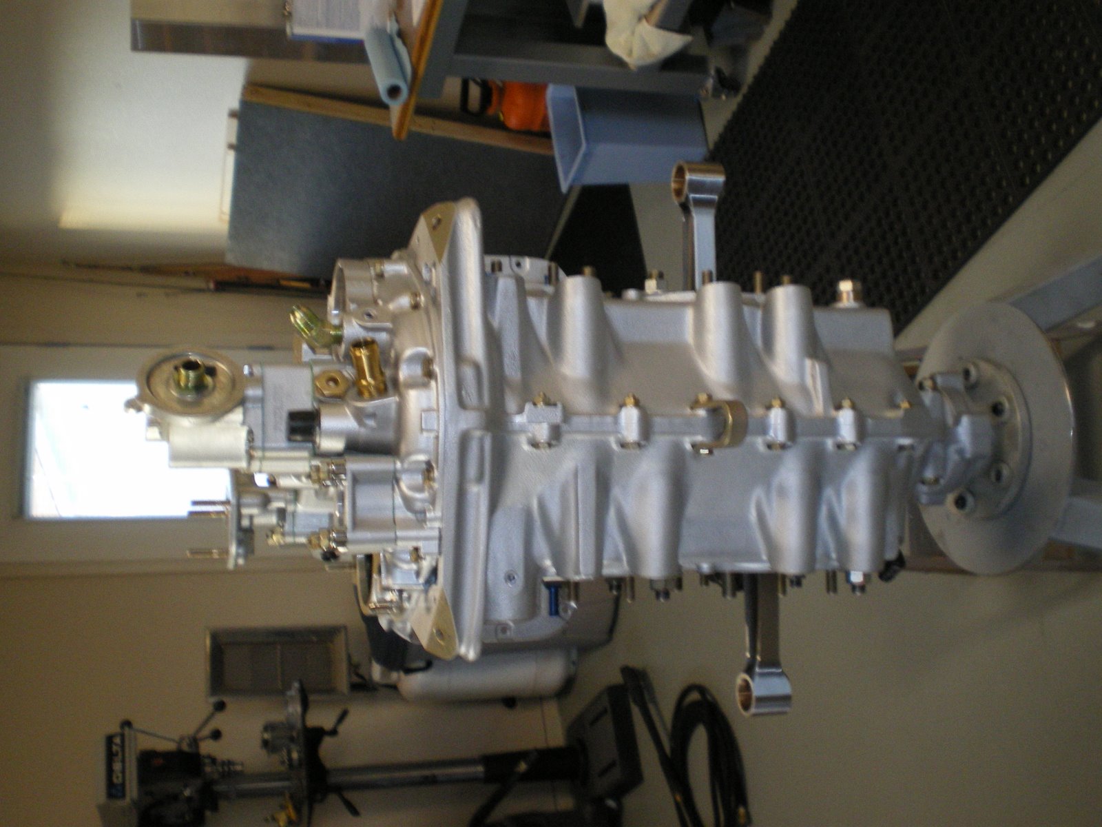
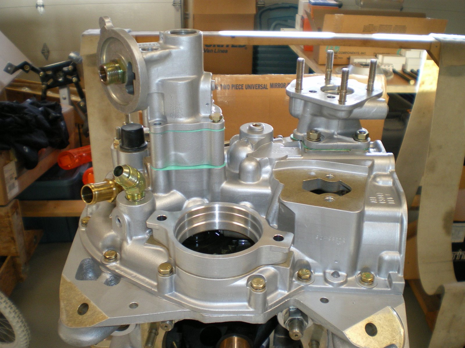
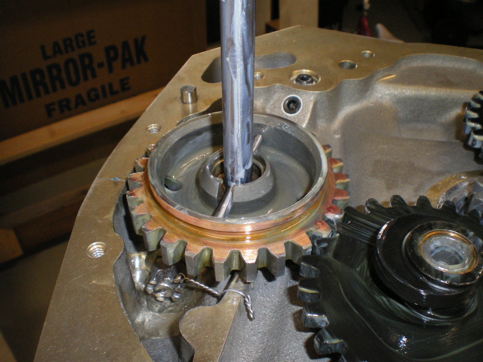
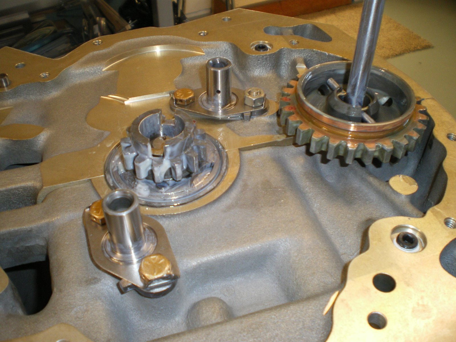
The engine is pretty much together now. I still have to install the mags, starter, and alt. I have to get the engine off the stand and mounted onto my horz rotating stand. I can put the front seal in and get the ring gear on. The front seal is always fun if it's not a split ring.
I purhcases some silicon rocker cover gaskets from Van's. I threw the cork gaskets away. They are leakers over time and you will back to installing silicon one. Pay atttention to the torque specs on the rocker cover screws with silicon gaskets. These are reusable gaskets. Covers are on and I have also installed the prop governor oil line. The clip they give you to hold the line down unders the cylinders is a little tight and pulls the line over too much. Looking through my pile of adel clamps, I found a longer one and installed it. It now is not in a bind at all. This will cut down on the stress of the line.
The engine is pretty much together now. I still have to install the mags, starter, and alt. I have to get the engine off the stand and mounted onto my horz rotating stand. I can put the front seal in and get the ring gear on. The front seal is always fun if it's not a split ring.
Saturday, August 9, 2008
Pushrods
I have called Aerosport and they say this is a common problem on brnad new engines. They will be sending me new 35's to do all of the intake rocker arms gaps. I had some older overhauled ones that look like they had the tips ground down a bit. I used them for trial fitting and they brought me down to .050 gaps. That's closer to the middle. I will be putting the new Lycoming ones in instead. This is a brand new engine and I will not have overhauled parts on it except for maybe the fuel injection servo. Not that overhauled parts are bad, it's just that I always wanted a new engine from the start. FedEx will have them to me by Monday morning and I will install on Monday afternoon. I will then get all of the valve covers installed and be ready to put on Mags. I still have to find out how many revolutions there is on the windup spring for the impulse coupling. Mine came undone and I have to wind it back up. After that the only thing left over will be the fuel injection system, starter and alt installations.
Tuesday, August 5, 2008
Installing rocker arms
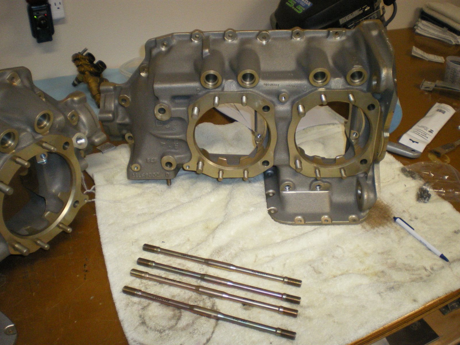
I tried installing the rocker arms and push rods. I have all 73434 push rods. The 34 indicates the length of the rod. 35, 36,37 are all increasinsly longer. They make these for overhauled engines that need longer rods to make up for material that has been ground off camshafts and tappets. I installed them by oiling down the push rods first. I took a syringe and sucked oil up into it. I then have a blunt needle that I put on and inject oil down inside the push rod. This gets some oil in there for startup and keeps out the corrosion out. I insert the rod into the tube and then set whatever cylinder I am working on at TDC on the compression stroke. I take the lubed up rocker arms and install the by pushing down on the push rod with the rocker arm and getting the rocker arm shaft lined up with all of the holes. It sounds easy but is harder when everything is lubed up and slick. Once both intake and exhaust are done it's get out the feeler gauges and check clearances on the arm to the stem/or cap. It needs to be >.028 and <.080. All of my intakes are over .080. Something is wrong. Lycoming used to have two styles of rocker arms, one for exhaust and one for intake. ECI sent one length of rods and one style of rocker arms. On a new engine I should not have over .080 valve clearance. I sent Aerosport a e-mail to see if I am doing it wrong or don't have the right parts. All of my other engines are flying around fine. Granted they were overhauled and I had to buy different lengths of pushrods. This is engine building and you have to do whatever it takes to make it right. So for now I will sit and wait. Maybe even have a beer!
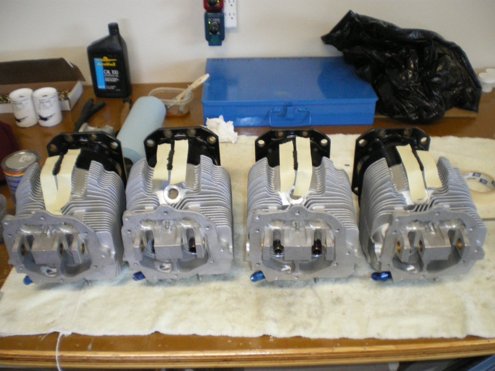
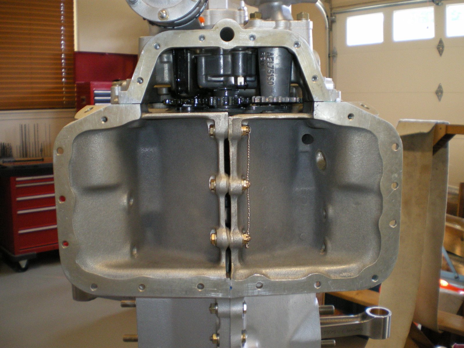
Installing all of the stuff under the cylinders
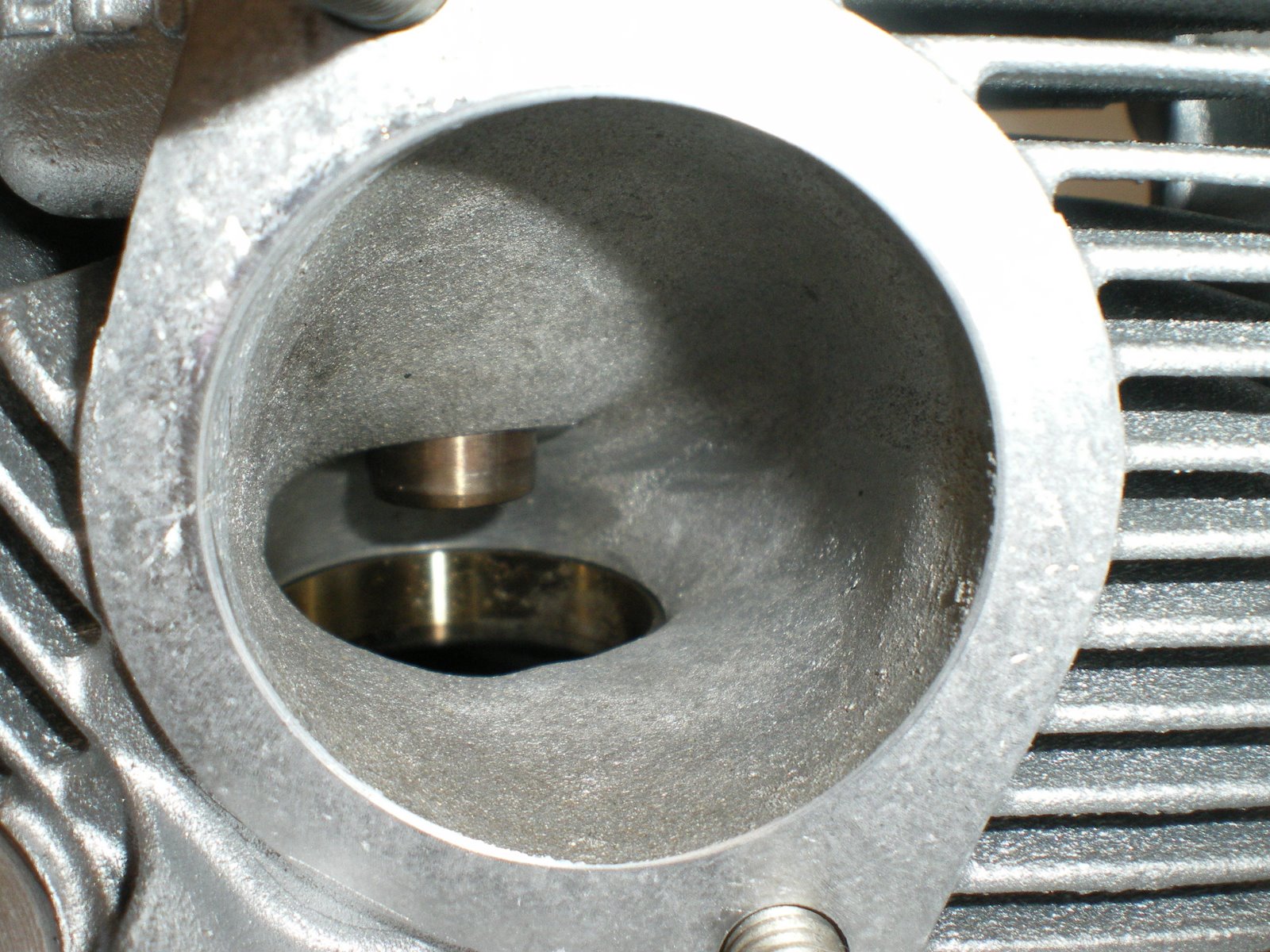
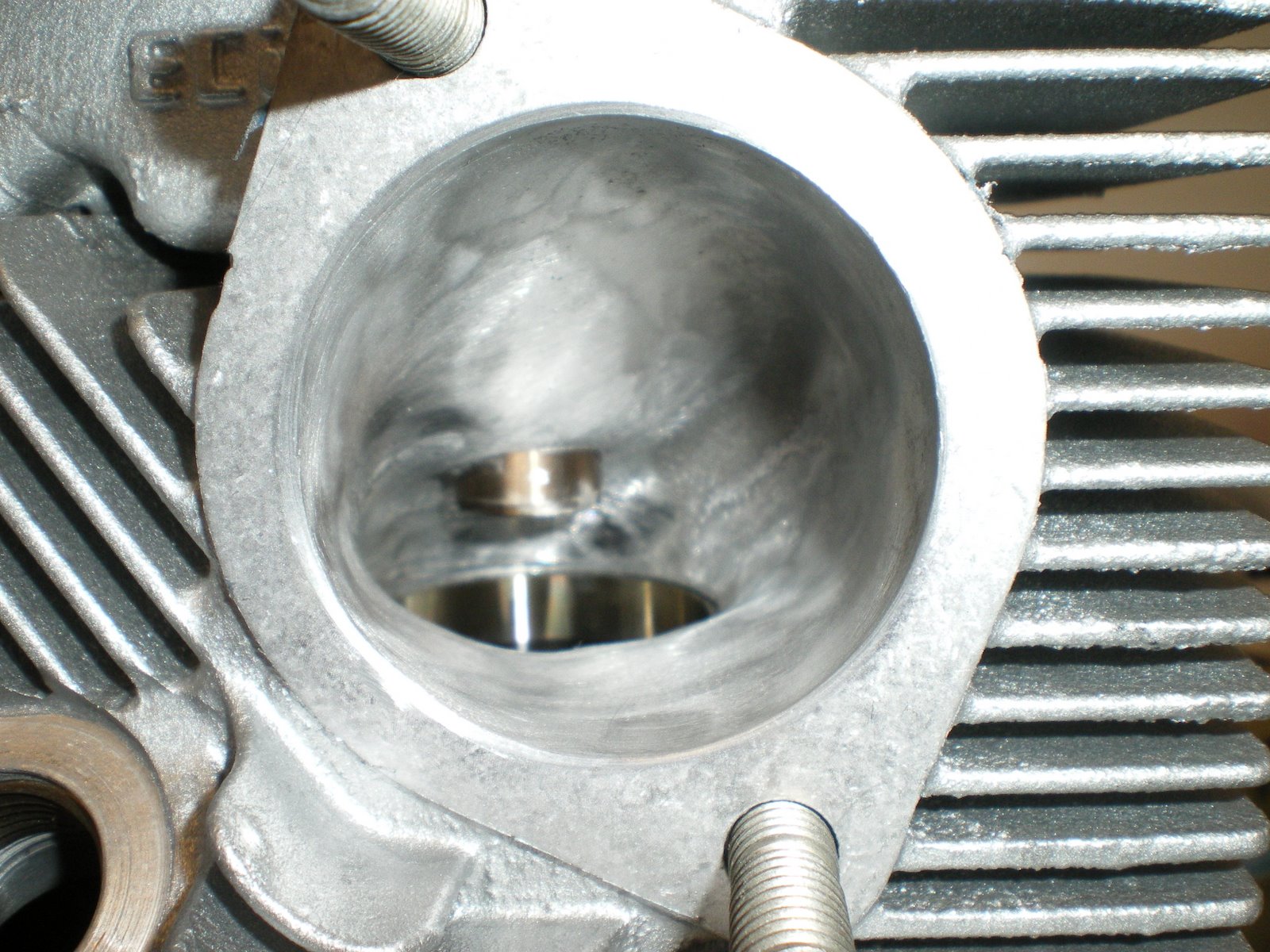
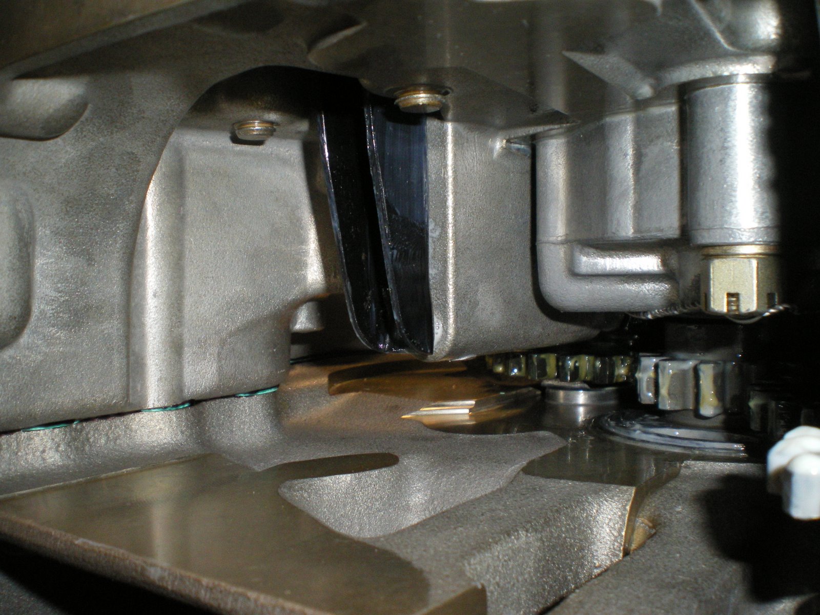
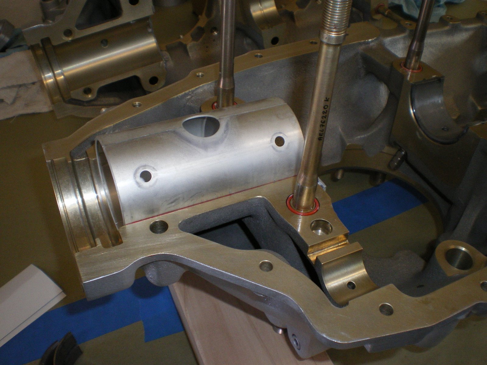
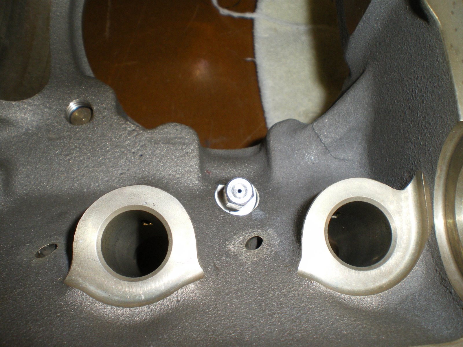
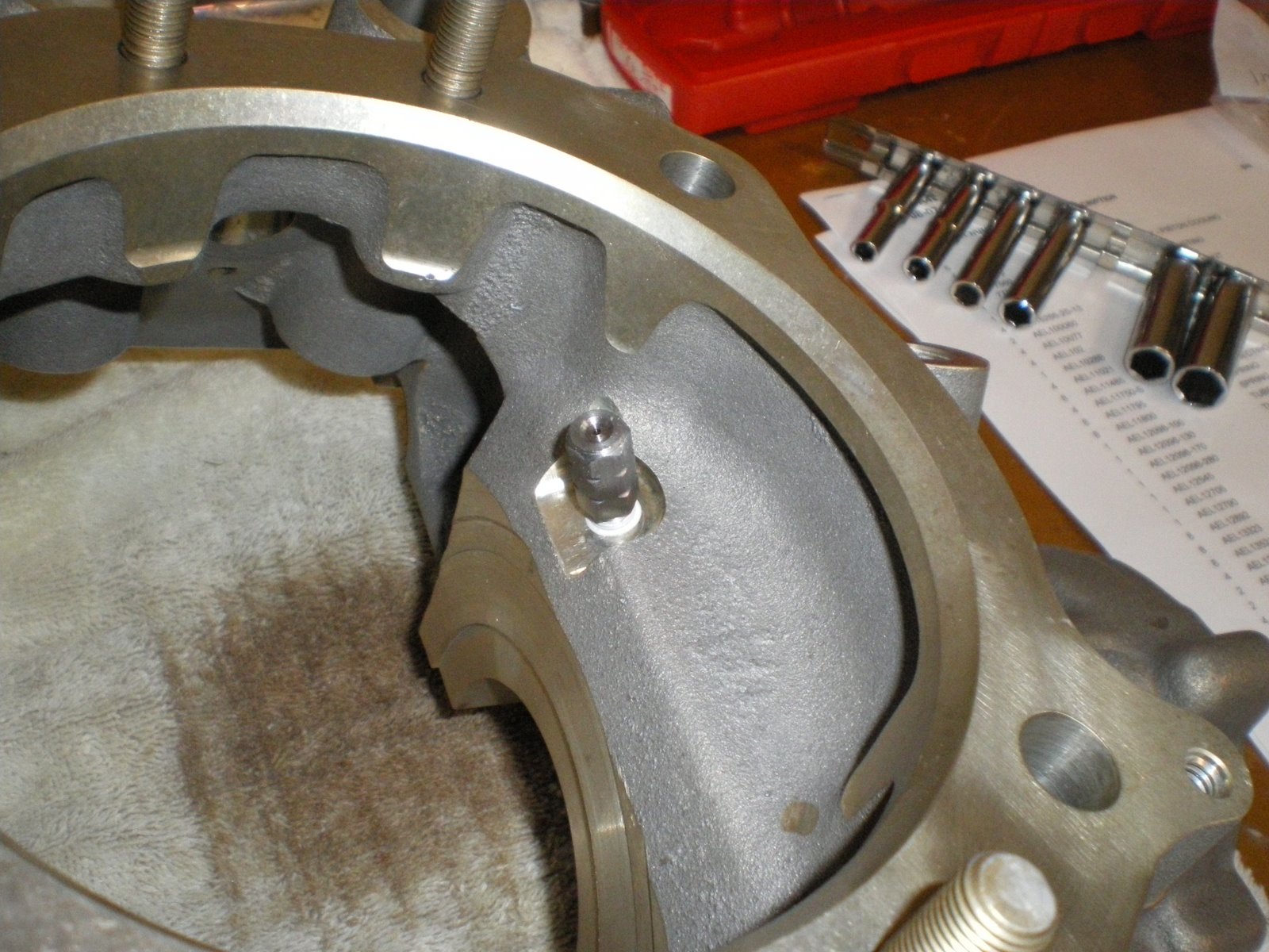
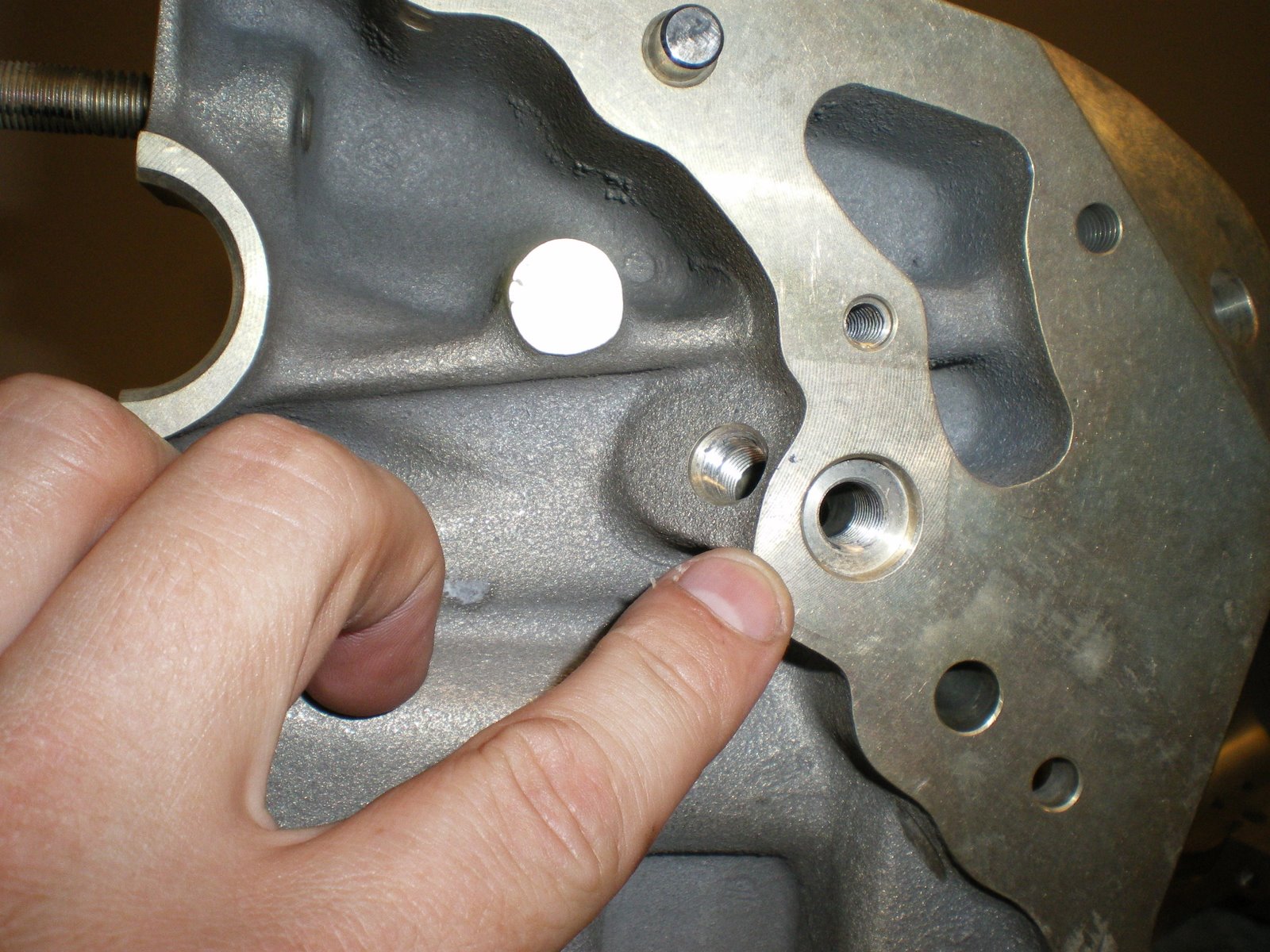
I have installed the intercylinder baffles. The are a major PITA to get on without scratching the paint on the fins. I got the tapered fin barrels and I thing that was a mistake. The baffles did not fit well and I had to grind off some material near the base and bend the heck out of the thing to get it to fit around the base. I also RTV'd the ledges of the baffles so they don't wear on the fins. I have pulled apart to many that were toasted from the fins wearing on the baffles. I installed the oil line drain tubes and I had to bend on those to get them to clear the bottom of the cylinder fins. Some things never change. Bash to fit, paint to match. I then installed the intake tubes. I learned my lesson on the last engine with the big 0-rings on the tubes. Lube up the o-rings and the inside of the plenum tube. Slowly rotate the intake pipe into the the plenum tube being careful not to push it in too hard. If it goes all the way into the plenum, you have to pull it back out. This will pinch or cut the o-ring and you'll have to drive all the way into town to get another one if you have a hydraulic shop close by. Some of the intake pipes fit pretty tightly to the bottom of the oil pan. They don't hit but don't miss by much either. I though I have it wrong but the tubes only can fit into one hole. Once this was all done I got all of the push rod tubes installed. Same thing here, lube the o-rings that go into the cylinder head. Pull the tubes while rotating at the same time and use a long socket that is the same diameter as the push rod tube to help push it in. It should kind of pop into place and you will not be able to push it farther. BTW, did I mention that you should install the plungers inside the tappets before you put the tubes in place. Don't fill them with oil because you will need to test for rocker arm gap once the rocker arms are installed. They will hydraulically load up and you will not be able to compress them.
Monday, August 4, 2008
Installing the cylinders
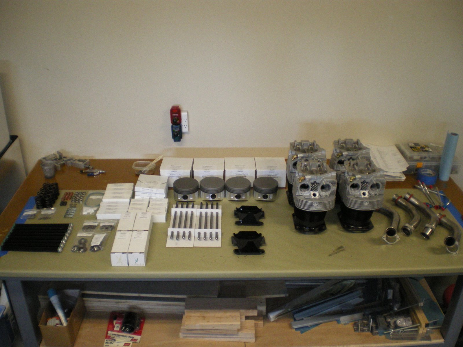
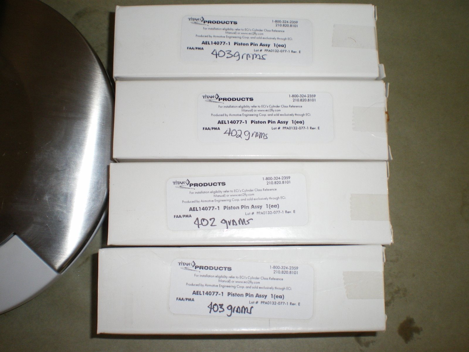
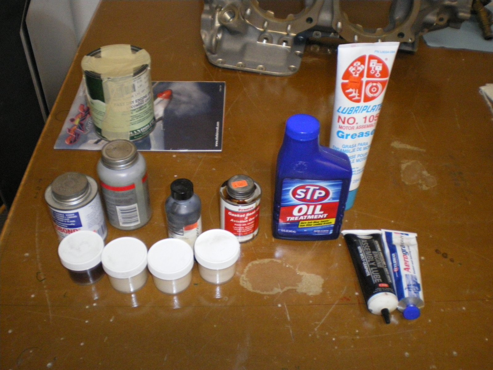
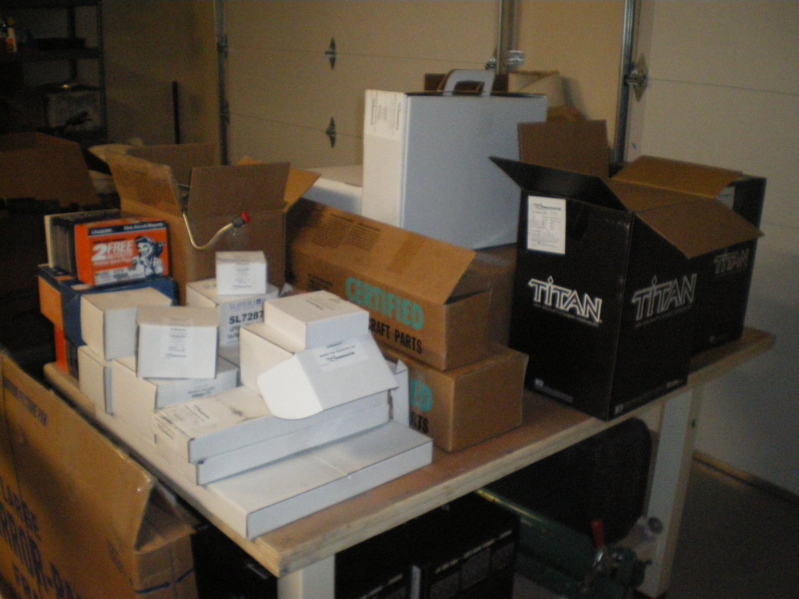
We installed the cylinders on the engine today. I started out by getting the bench all cleaned up and organized. I logged all of the lot numbers on my parts sheet that will be loaded into the computer later on so I have a computer file of my engine parts that can be accessed at whim. I also got out the tools needed to put the cylinders together.
Torque wrenches, cylinder wrenches, ring compressor, rign expander pliers, valve compressor, picks, magnet on a stick (for valve keepers), flashlight and more. Get all of the this stuff ready to go because when you start compressing valves it needes to be a quick reach.
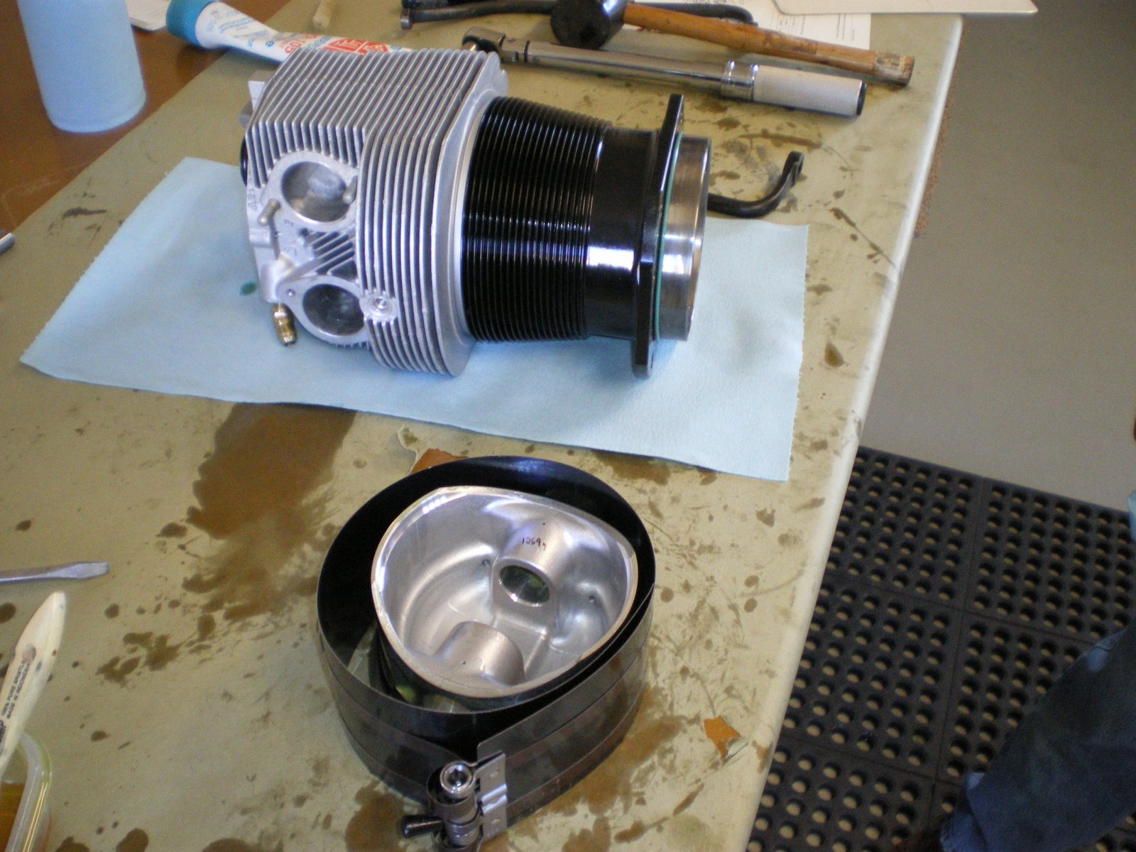
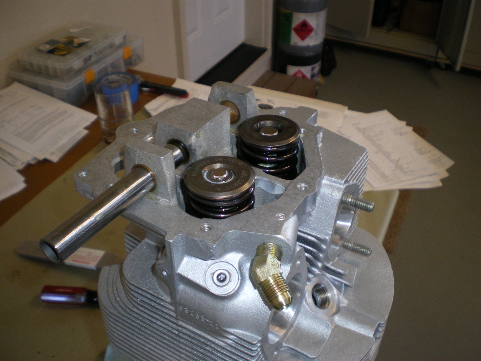
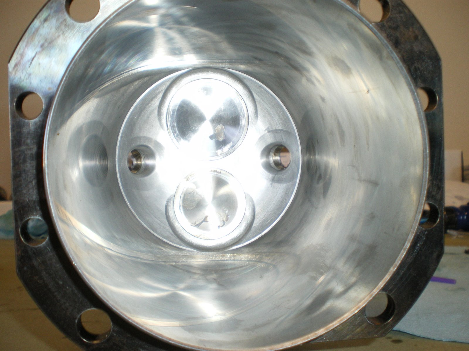
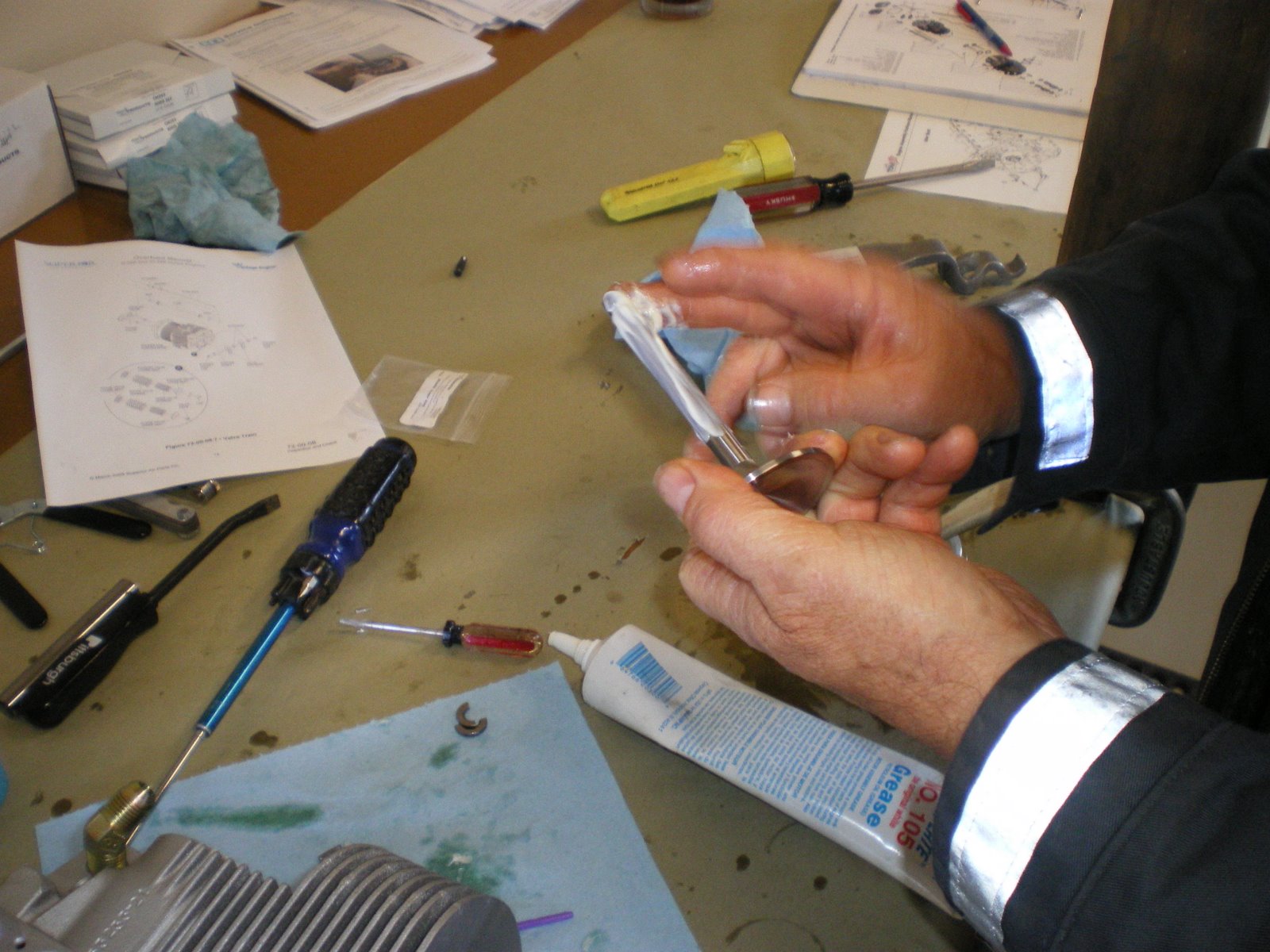
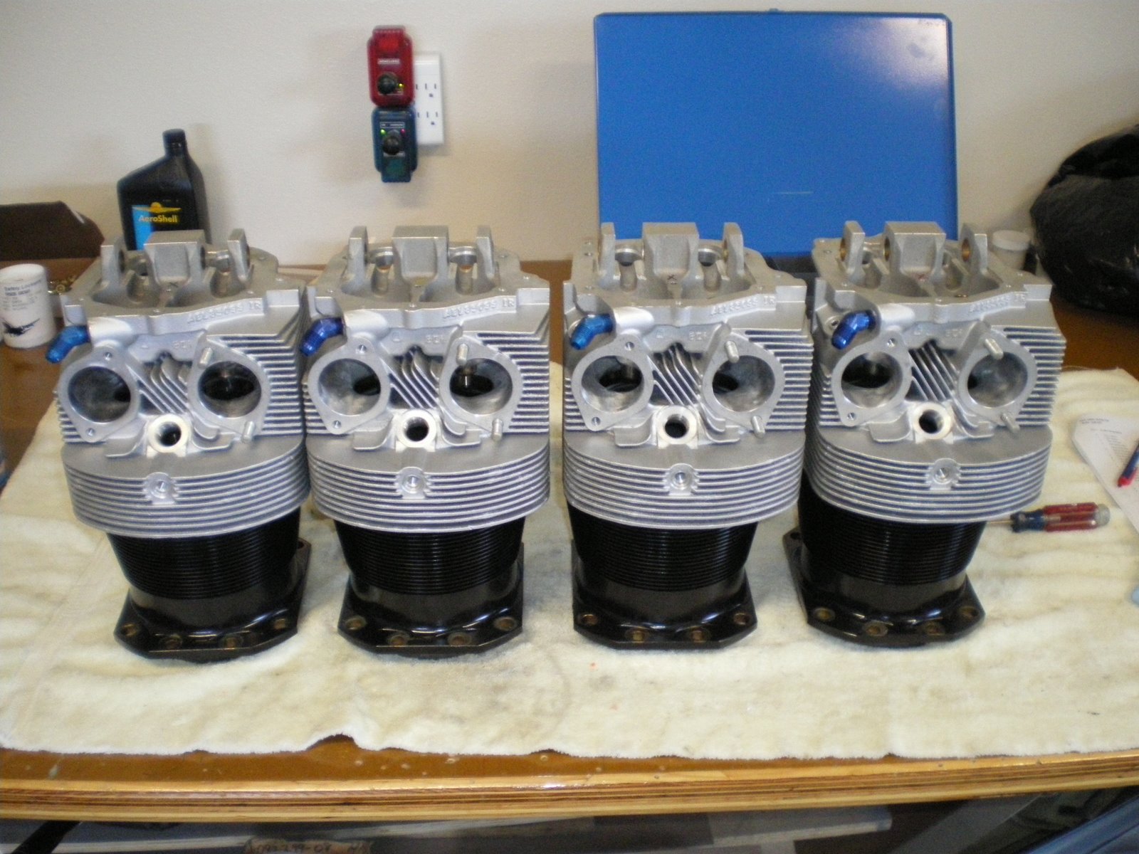
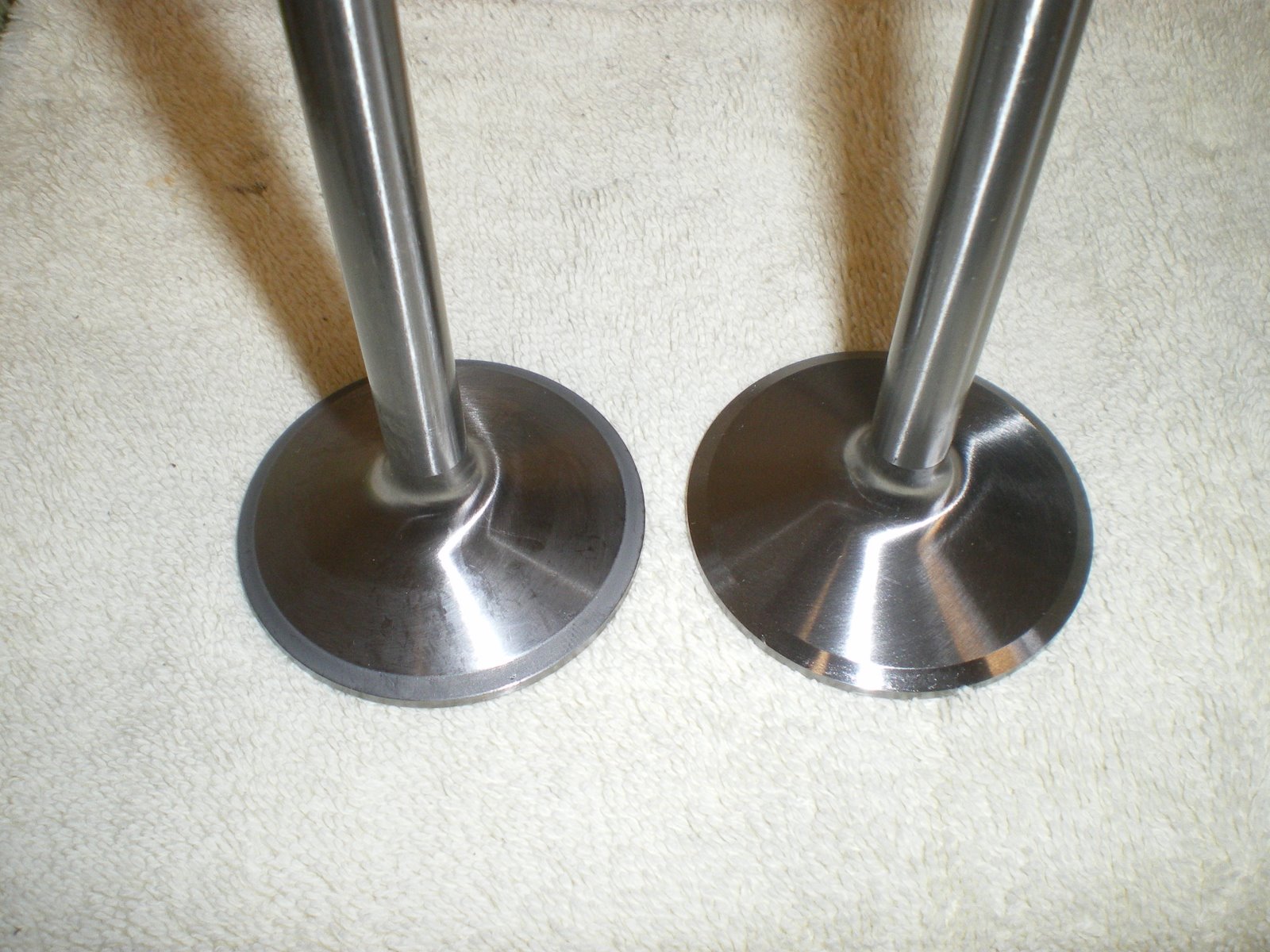
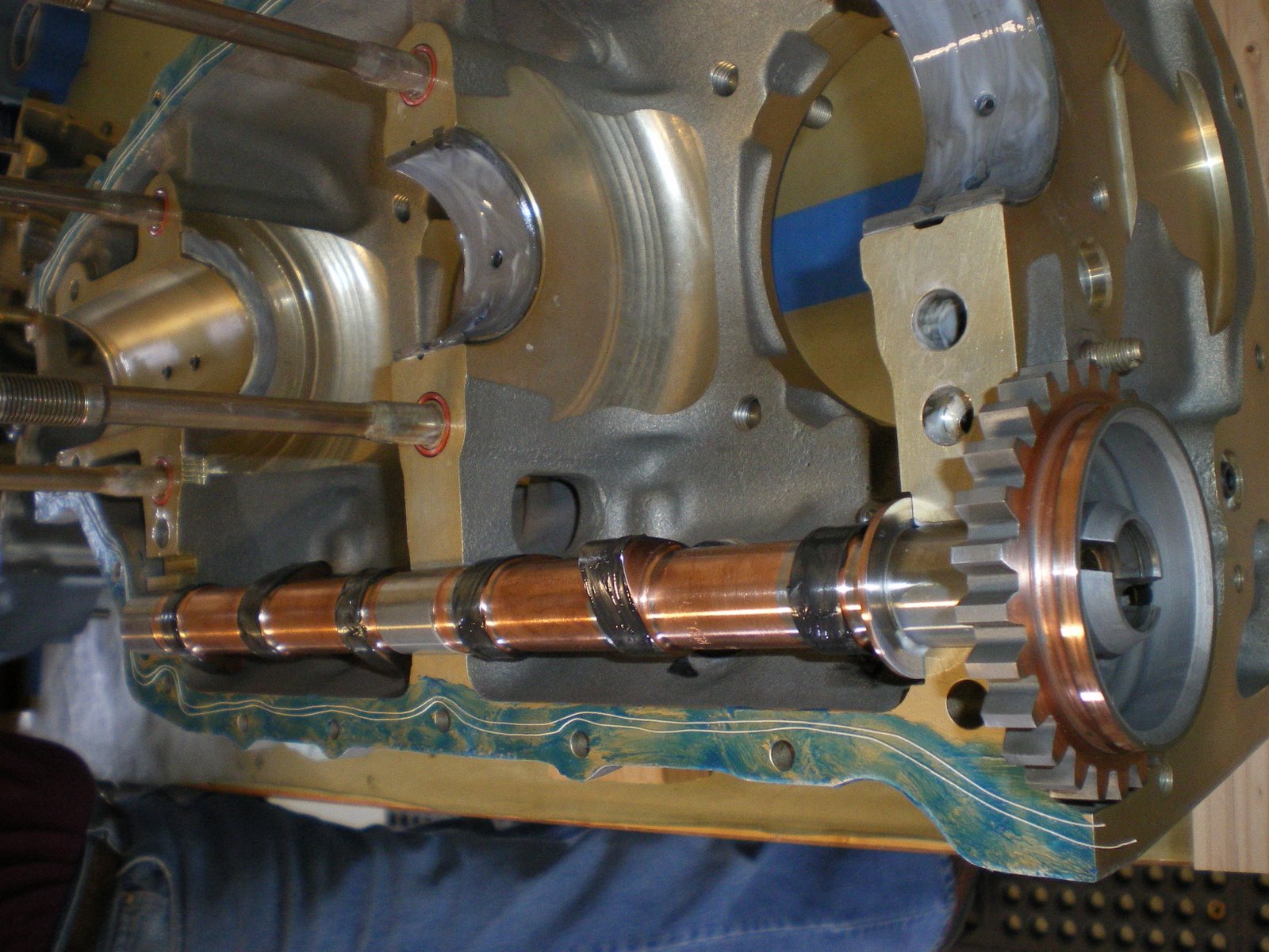
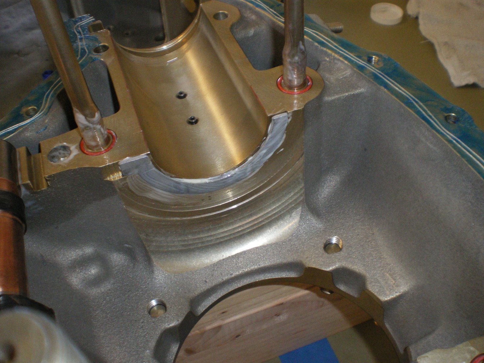
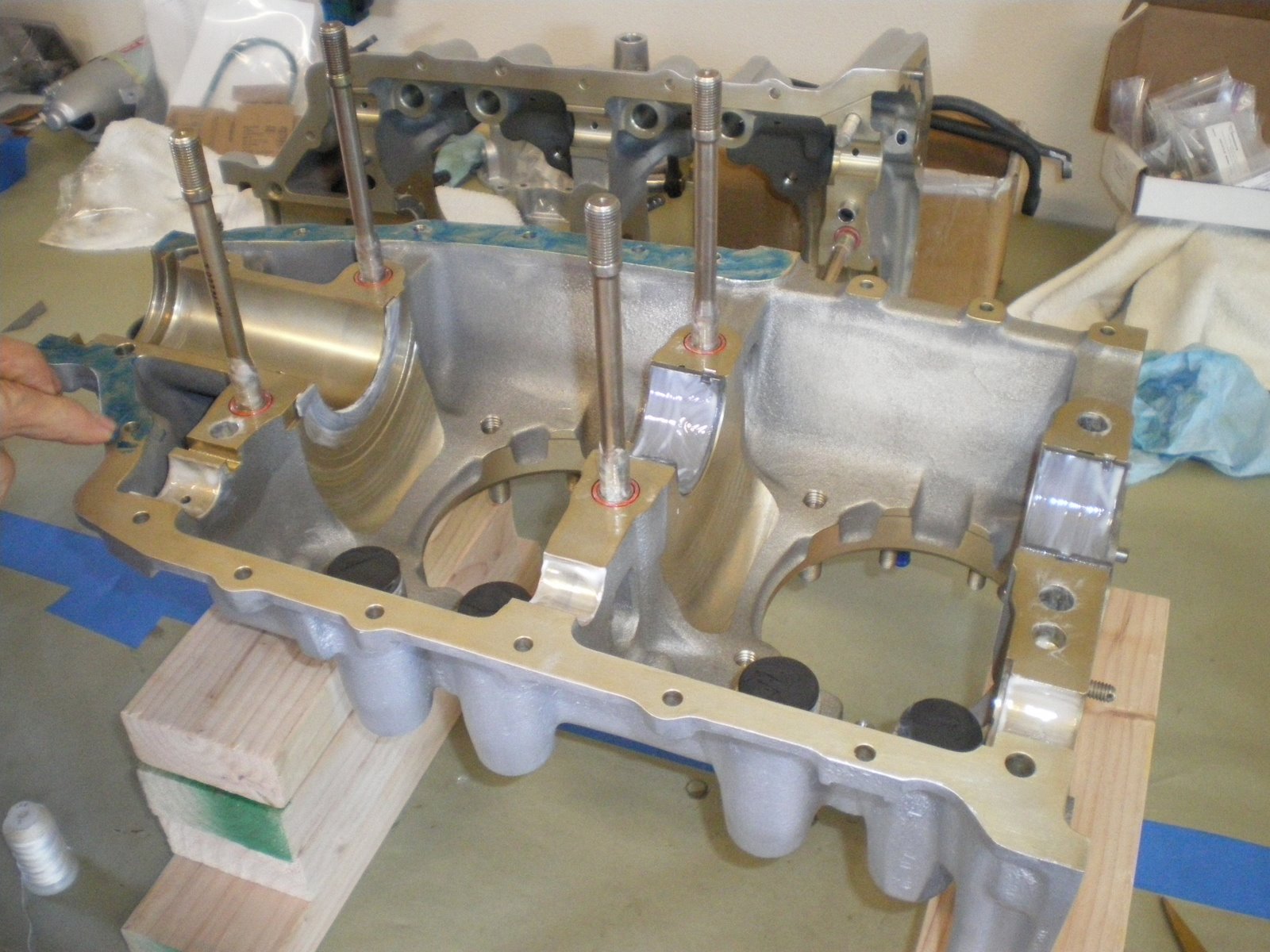
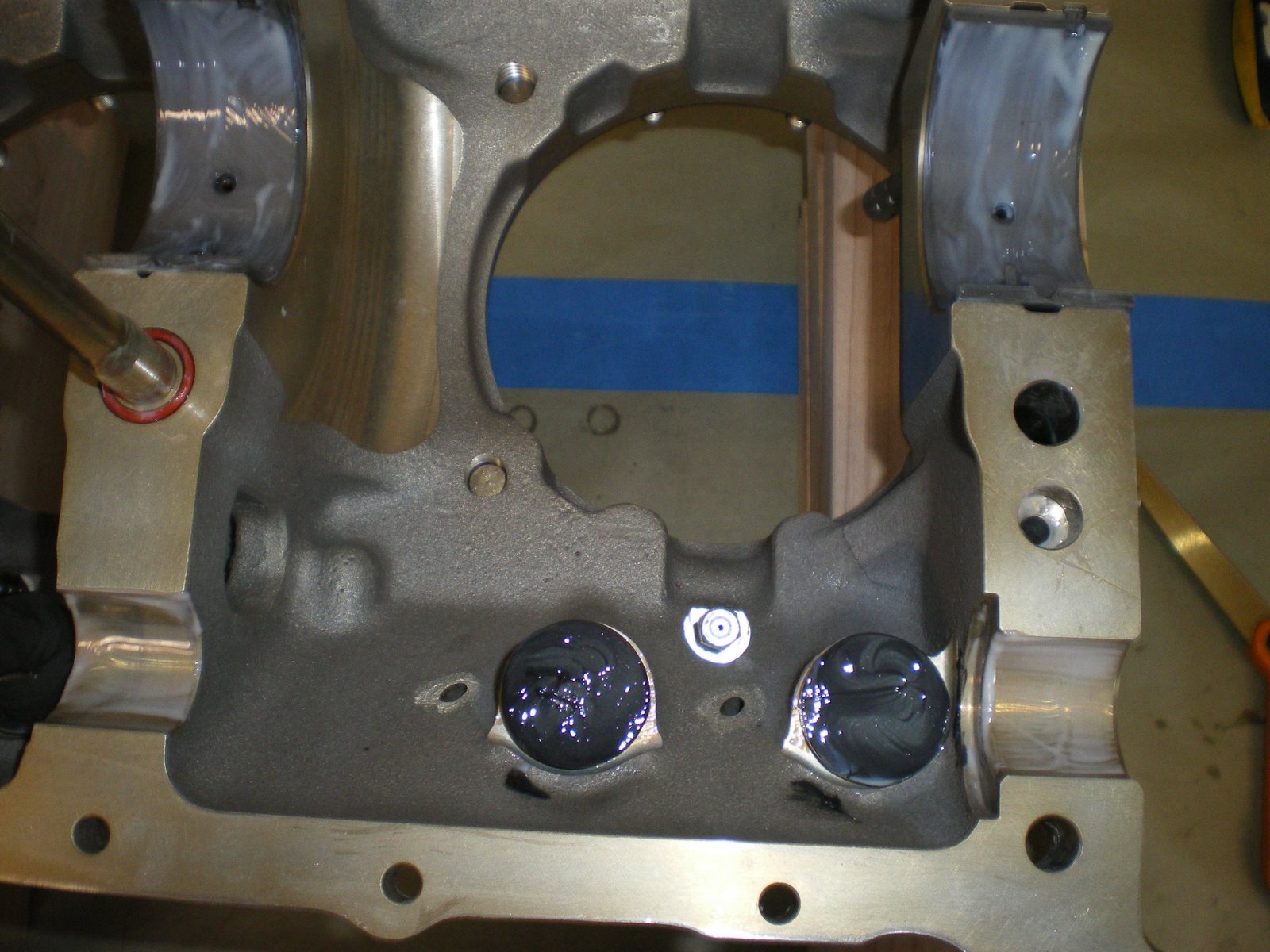
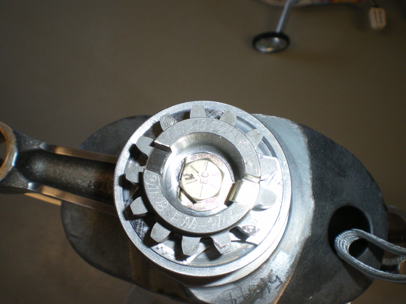
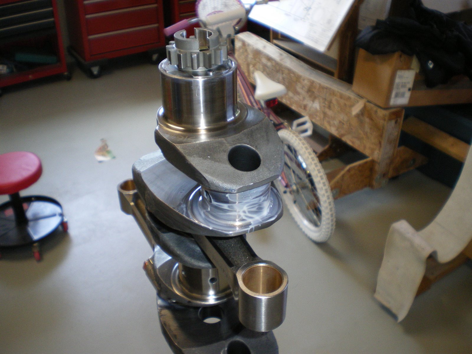
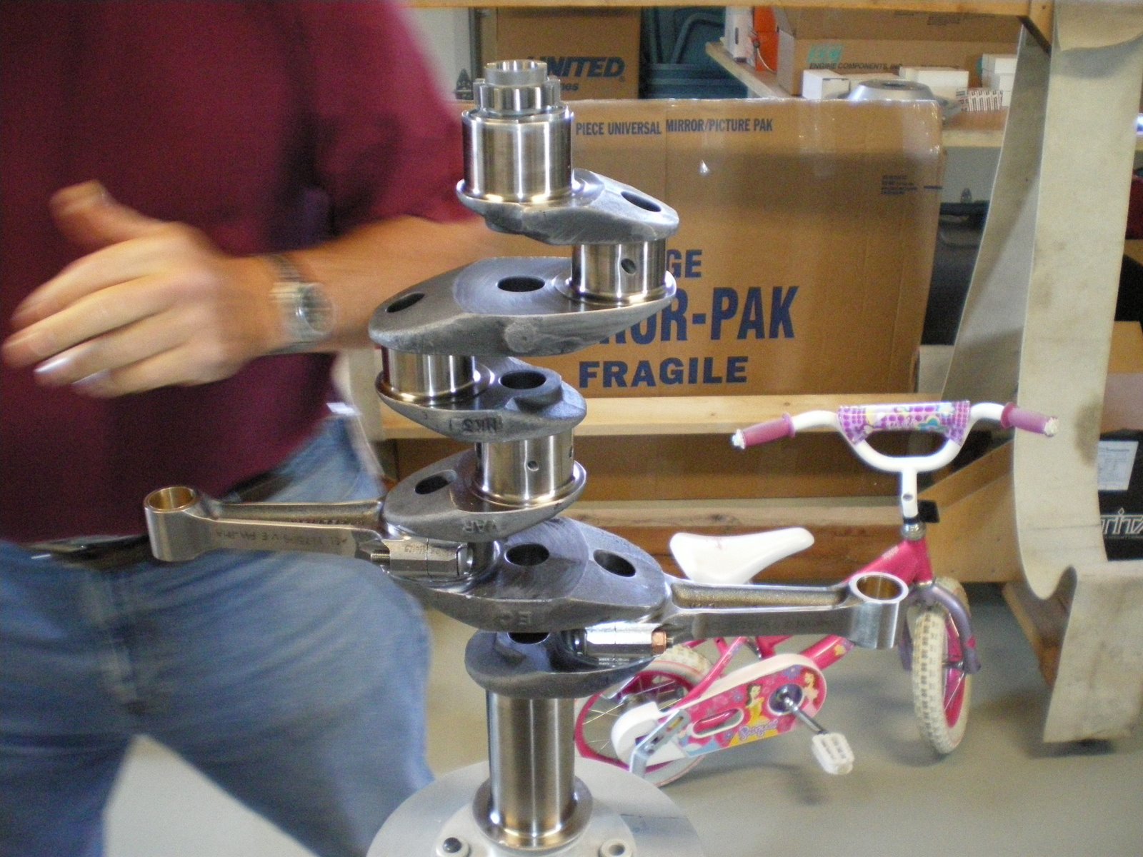
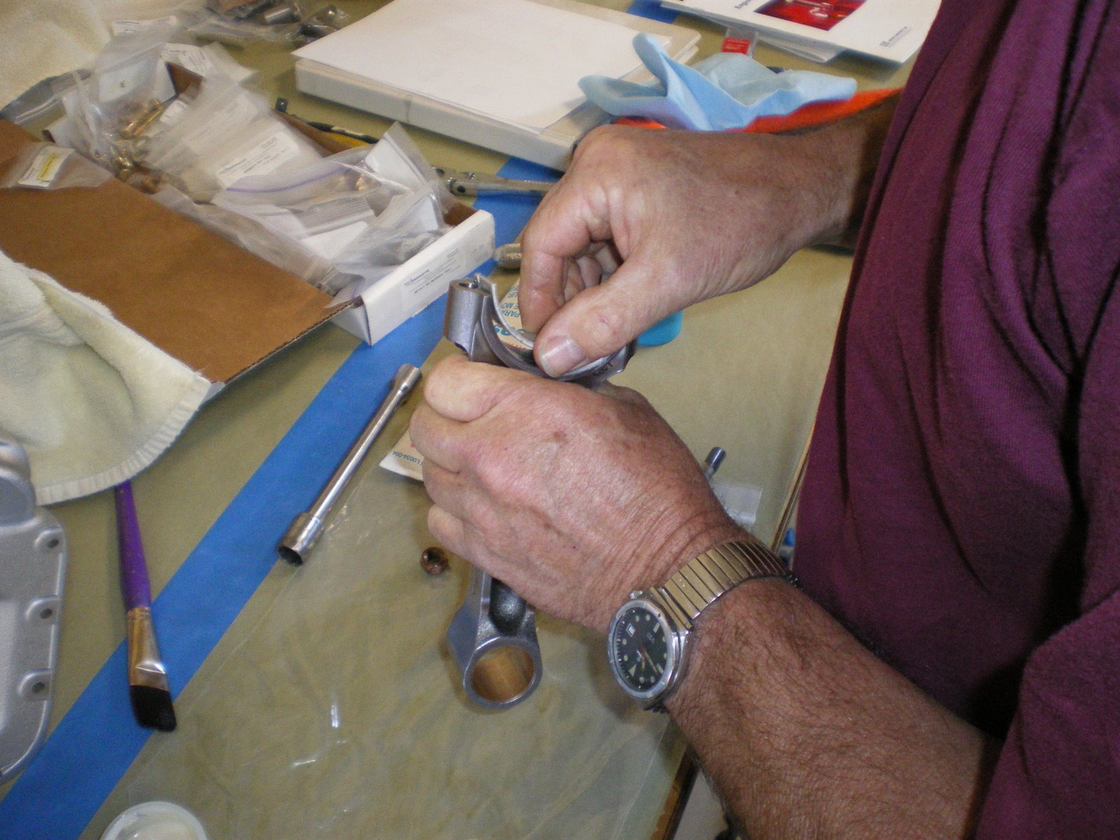
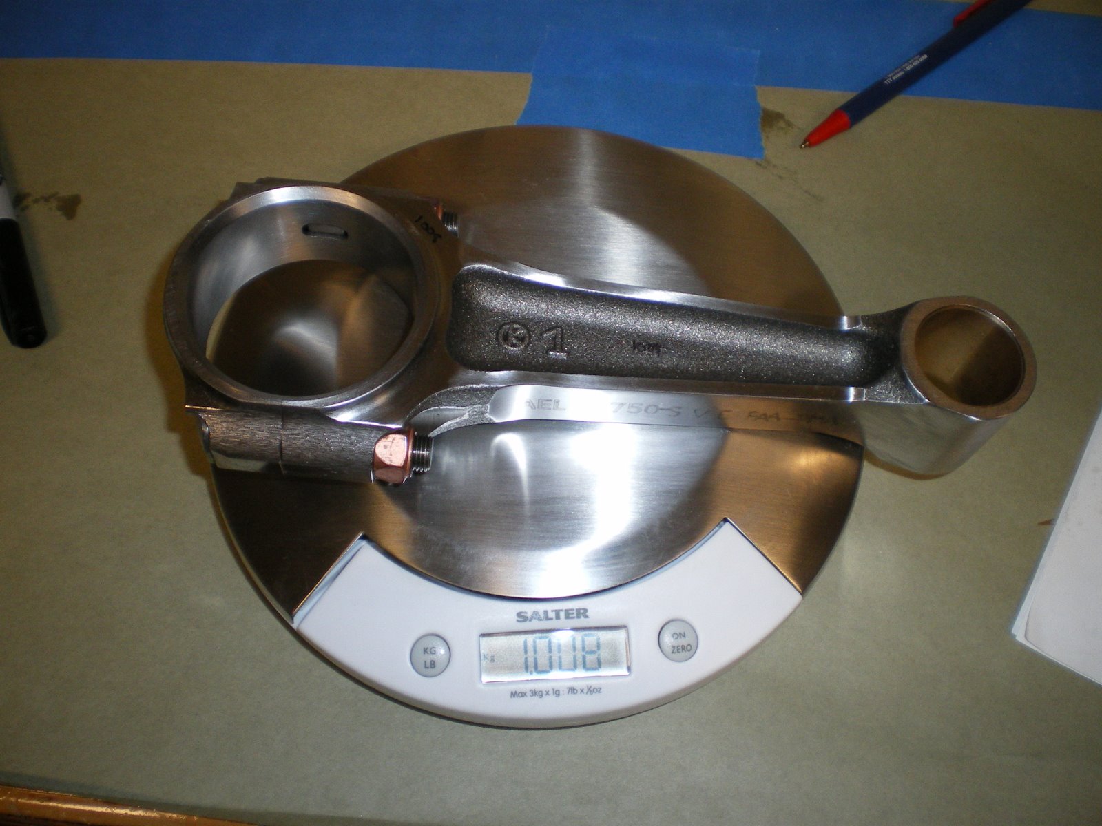
We start off by putting the valves in the cylinders. Clean the guides, lube the stems and install making sure not to scratch the valve stems. Remember earlier, I lapped the valves and kept the cylinders and valves together. I mounted our hi-tech valve keeper-inner on the bench which is a post with angles on it and the top has been rounded. I clamped it to the bench and when you get your valves in place you hang onto the stems and have someone pick up the cylinder. You lower it down onto the post and this will help keep the valve seated while you push down on them with the spring compressor. Next you oil up the valve seats top and bottom. There is not a difference on the bottom ones but there is on the top. The cone shape one goes on the intake stem. Get your springs out and lube them up and make sure they are the right way facing up. Put them on the seat over the stem and install the top seat. Install the rocker arm shaft and take your brand new valve spring compressor and push the springs down. This a two person job. One person holds onto the cylinder and does the compressing. The other person guides the top seat over the stem so it does not scrap the valve stem. Have you keeper ready to go and install. The exhaust ones are like half shaped circles. You put them in under the hole in the spring compressor (there a arc in it for this purpose) with your screw diver. You put one in and then rotate it around to back side. Install the other opposing it and then slowly let off on the spring. It should push the keeper up and seat it in the groove in the stem. DON'T let the keeper turn up or down it has to lay in there flat. Once that it done move onto the intake steam. These keepers are a little different in that they are more cone shaped. I used some Lubraplate and put some on the inside of the keeper. This holds it onto the stem while you let up on the compressor. Compress the spring and take your magnet and put the keeper on it pointing down. Lower it down into the compressor hole and then use a pick or small screw driver to push it off the magnet and push it up against the stem. There is a notch in the stem and curb on the keeper, so you will feel it go into place. Do the same for the other side. Once they are both done and oppose one another, slowly raise the compressor and it will seat the keepers on the stem. If the keepers are cocked or look wrong then put the pressure back on the compressor and adjust them until they seat. By the 4th cylinder your a pro. They have special tools besides the compressors that make all of this easy. However, this is on the cheap so we are doing it the harder way. Use lots of oil and snot to coat things up. Once you are done, put the cylinder in a box upside down to drain off excess oil into a rag. This will keep it all from running down the engine on the stand.
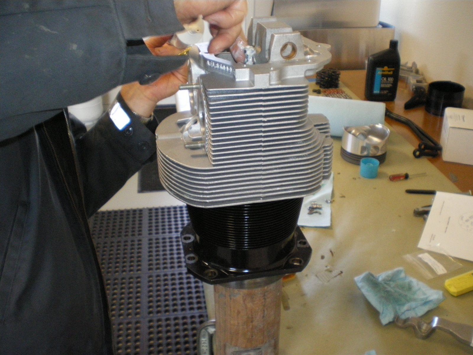
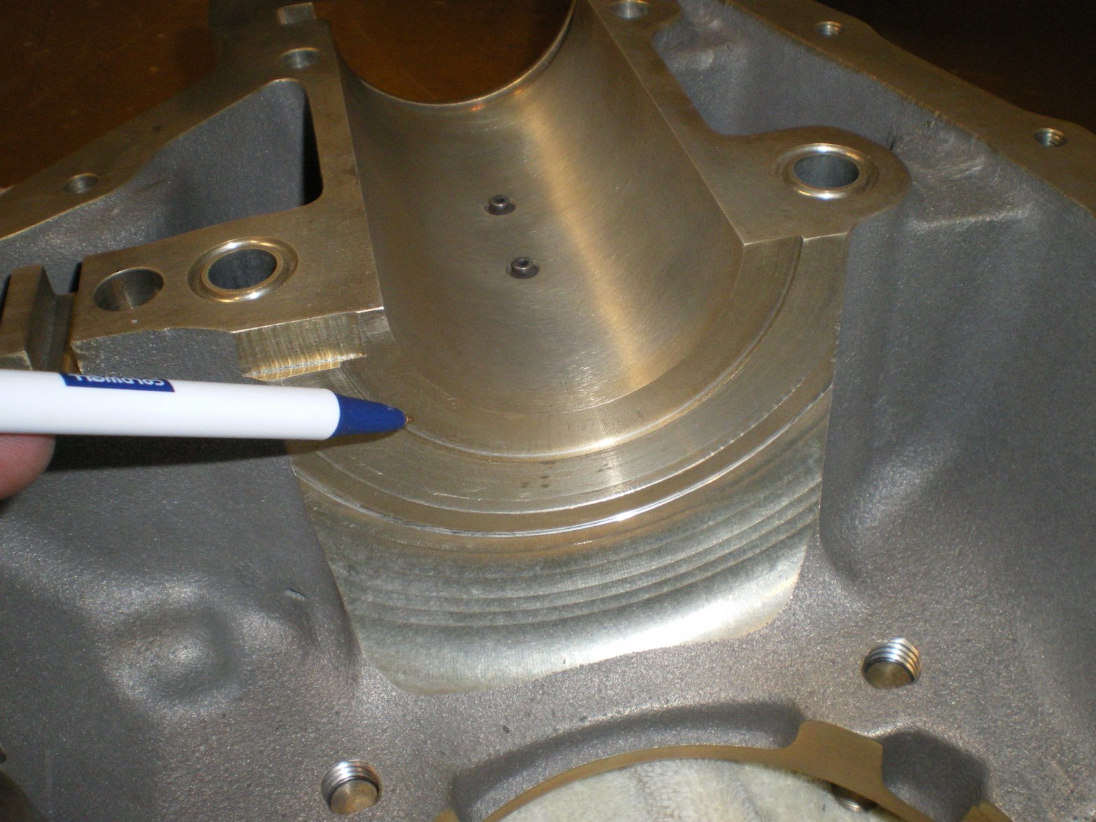
Once all 4 cylinders are done, start with the rings on the piston and install it in the cylinder. The rings are clearly marked and there is a bulletin on ECI website that gives you clearances and ring gap orientation. We checked ring gap and top stroke and it was above the .0075 min. We lubed up the rings and installed them on the cylinder. The top and bottom ring gaps are lined up with the middle ring gap is 180 degress opposite of it. Superior has them at 10 and 2. Why, I have no idea. Once that is done lube up the cylinder walls with MINERAL oil and make sure there is not grit in there. Lube up the piston and put the compressor on it. Compress the rings making sure not the turn them, put the piston over the cylinder bore and push the piston out a bit just so the top sticks out. Push this chamferred area into the bore and them push the piston down into the bore. Make sure you oriented the piston to go it with the wrist pin holes pointing the right way. You don't want to turn the piston anymore than you have to. Only insert the piston into the bore enough so the rings don't come out. Get your cylinder wrist pin lube up and then start it into the piston. Take the cylinder over to the engine and install it on the engine. We installed the #2 cylinder first because these are the first thru studs that get torqued in the sequence. Install the bottom o-ring seal on the cylinder before you put it on. Take the cylnder over to the engine, have someone line up the wrist pin the con rod and slide it thru. Then push the cylinder down onto the studs and install the hold down nuts. THERE IS THREE SEQUENCES TO FOLLOW. 1. The case torque sequence 2. The big cylinder hold down nuts 3. The little cylinder hold down nuts. So do each cylinder as you need to for the case/thru bolt sequence then torque each one as the manual shows. We did not torque the big hold down nuts on cylinders to full 600 in/lbs until we had all cylinders on the engine. Once they are all on, torque to full amount using the torque sequence in the manual. Don't worry if you hear some squeaking noises when you torque the big nuts on the thru bolts. They are just stretching a bit. I go through the sequence twice and give a little time between cycles. You'll be suprised how much the thru bolts stretch on the second cycle. Once this is all done you can start installing the rest of the stuff as follows.
1. Intercylinder baffles.
2. Cylinder oil drain tubes.
3. Intake tubes.
4. Push rod tubes,
5. Push rod retainers with lock plate.
By this time you will have oiled everthing down in your shop including yourself. Probably have all of your tools out and have gone through about 3 rolls of paper towels. Enjoy.
Torque wrenches, cylinder wrenches, ring compressor, rign expander pliers, valve compressor, picks, magnet on a stick (for valve keepers), flashlight and more. Get all of the this stuff ready to go because when you start compressing valves it needes to be a quick reach.
We start off by putting the valves in the cylinders. Clean the guides, lube the stems and install making sure not to scratch the valve stems. Remember earlier, I lapped the valves and kept the cylinders and valves together. I mounted our hi-tech valve keeper-inner on the bench which is a post with angles on it and the top has been rounded. I clamped it to the bench and when you get your valves in place you hang onto the stems and have someone pick up the cylinder. You lower it down onto the post and this will help keep the valve seated while you push down on them with the spring compressor. Next you oil up the valve seats top and bottom. There is not a difference on the bottom ones but there is on the top. The cone shape one goes on the intake stem. Get your springs out and lube them up and make sure they are the right way facing up. Put them on the seat over the stem and install the top seat. Install the rocker arm shaft and take your brand new valve spring compressor and push the springs down. This a two person job. One person holds onto the cylinder and does the compressing. The other person guides the top seat over the stem so it does not scrap the valve stem. Have you keeper ready to go and install. The exhaust ones are like half shaped circles. You put them in under the hole in the spring compressor (there a arc in it for this purpose) with your screw diver. You put one in and then rotate it around to back side. Install the other opposing it and then slowly let off on the spring. It should push the keeper up and seat it in the groove in the stem. DON'T let the keeper turn up or down it has to lay in there flat. Once that it done move onto the intake steam. These keepers are a little different in that they are more cone shaped. I used some Lubraplate and put some on the inside of the keeper. This holds it onto the stem while you let up on the compressor. Compress the spring and take your magnet and put the keeper on it pointing down. Lower it down into the compressor hole and then use a pick or small screw driver to push it off the magnet and push it up against the stem. There is a notch in the stem and curb on the keeper, so you will feel it go into place. Do the same for the other side. Once they are both done and oppose one another, slowly raise the compressor and it will seat the keepers on the stem. If the keepers are cocked or look wrong then put the pressure back on the compressor and adjust them until they seat. By the 4th cylinder your a pro. They have special tools besides the compressors that make all of this easy. However, this is on the cheap so we are doing it the harder way. Use lots of oil and snot to coat things up. Once you are done, put the cylinder in a box upside down to drain off excess oil into a rag. This will keep it all from running down the engine on the stand.
Once all 4 cylinders are done, start with the rings on the piston and install it in the cylinder. The rings are clearly marked and there is a bulletin on ECI website that gives you clearances and ring gap orientation. We checked ring gap and top stroke and it was above the .0075 min. We lubed up the rings and installed them on the cylinder. The top and bottom ring gaps are lined up with the middle ring gap is 180 degress opposite of it. Superior has them at 10 and 2. Why, I have no idea. Once that is done lube up the cylinder walls with MINERAL oil and make sure there is not grit in there. Lube up the piston and put the compressor on it. Compress the rings making sure not the turn them, put the piston over the cylinder bore and push the piston out a bit just so the top sticks out. Push this chamferred area into the bore and them push the piston down into the bore. Make sure you oriented the piston to go it with the wrist pin holes pointing the right way. You don't want to turn the piston anymore than you have to. Only insert the piston into the bore enough so the rings don't come out. Get your cylinder wrist pin lube up and then start it into the piston. Take the cylinder over to the engine and install it on the engine. We installed the #2 cylinder first because these are the first thru studs that get torqued in the sequence. Install the bottom o-ring seal on the cylinder before you put it on. Take the cylnder over to the engine, have someone line up the wrist pin the con rod and slide it thru. Then push the cylinder down onto the studs and install the hold down nuts. THERE IS THREE SEQUENCES TO FOLLOW. 1. The case torque sequence 2. The big cylinder hold down nuts 3. The little cylinder hold down nuts. So do each cylinder as you need to for the case/thru bolt sequence then torque each one as the manual shows. We did not torque the big hold down nuts on cylinders to full 600 in/lbs until we had all cylinders on the engine. Once they are all on, torque to full amount using the torque sequence in the manual. Don't worry if you hear some squeaking noises when you torque the big nuts on the thru bolts. They are just stretching a bit. I go through the sequence twice and give a little time between cycles. You'll be suprised how much the thru bolts stretch on the second cycle. Once this is all done you can start installing the rest of the stuff as follows.
1. Intercylinder baffles.
2. Cylinder oil drain tubes.
3. Intake tubes.
4. Push rod tubes,
5. Push rod retainers with lock plate.
By this time you will have oiled everthing down in your shop including yourself. Probably have all of your tools out and have gone through about 3 rolls of paper towels. Enjoy.
Subscribe to:
Posts (Atom)


.JPG)