Saturday, March 7, 2009
Finishing the right elevator
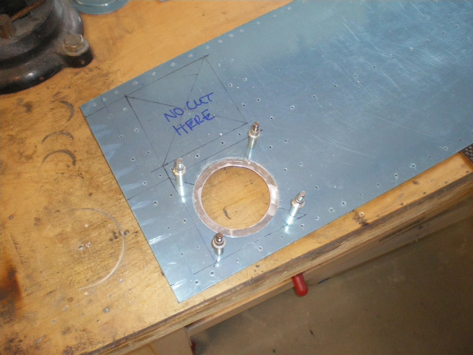
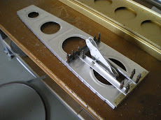
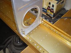
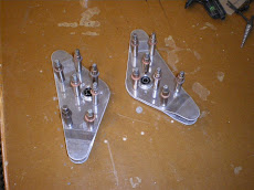
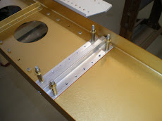
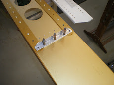
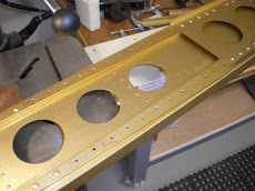
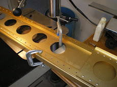
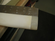
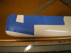
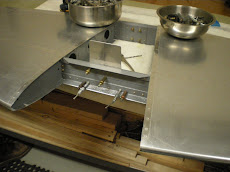
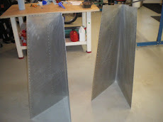
The elevator is made the same way as the rudder-in V blocks aligned on the bench. The major difference to the rudder is that there are counter balances that go forward of the hinge line to offset the weight of the elevator. This makes the controls feel very light and it also reduces the chances flutter in flight. Flutter can rip the control surfaces right off the airplane. It mostly applies to airplanes flying over 200mph. You assemble the skins with the stiffeners and the skeleton then put it in the jig and drill the end ribs to the skins to set you alignment. The spar and skins come predilled. Deburr and dimple all your new holes then it's back into the jig for riveting. All except the tip end where the counter balance is at. You have to fit the conter balance and weight to the tip and drill it all in place. You have to pay attention to the two end ribs and make sure they don't twist during the drilling process. This will give you uneven gaps between your horz stab and elevator. You will see this uneven gap and it will stand out like a sore thumb. Once it's all drilled, you debur , dimple, and prime the inside of the counter balance. Assemble it all together and rivet. Make the tip fit and pop rivet the tip on. Next comes the epoxy/floc you have to do to fill in the end over the counter balance weight. It will have to be molded and then all sanded and filled before painting. I usually wait to do all the tail fiberglassing at once because it sucks.
Finish the Rudder
I have finished the rudder some time ago and I am just getting around to posting the pictures. The rudder has it's own challanges in that it has the rudder horn and tail light in it to build. Getting the bottom rudder fairing to fit correctly is also a PITA.
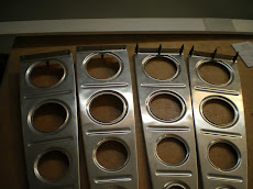
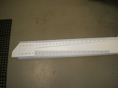
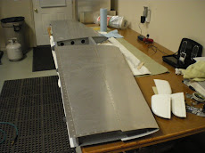
Some time back I primed all the parts and assembled the skeleton of the rudder. I then backriveted the stiffeners to the skin. I backrivet as much as I can because it gives you a smoother skin surface overall and it all adds up to drag if your skins are not smooth.
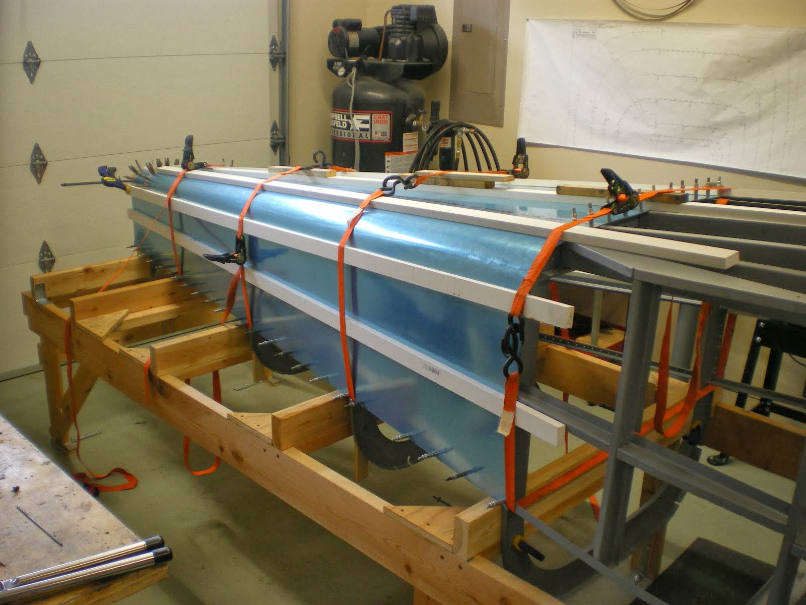
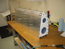
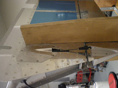
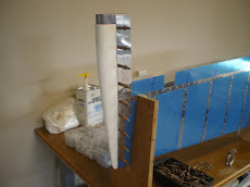
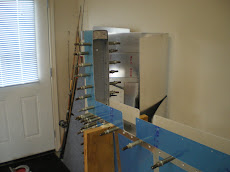
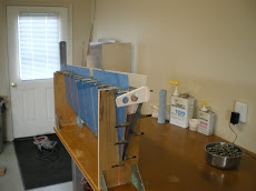
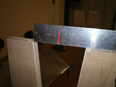
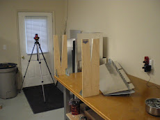
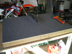
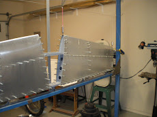
Next comes the jigs. I found some extra plywood from a felt box down at the mill and hauled it home. 3/4" plywood makes some nice jigs. I measured the spots on the skeleton where I wanted the skin supported and then measured the skin V at each location. I then transferred this to the plywood and cut them all out using the skil saw and cut the V's in the band saw. I then squared up the edges on the disc sander so the jig would be square to the bench. I leveled my bench top and then made a centerline on the table top. I made 90 degree lines from the centerline at each jib location and them attached the jig to the table top with brackets and laser aligned the top and bottom of the V's on the jig so that there is no twist in the two V's relative to each other and everything is centerlined to the table top. It is critical that you get this right as your control surfaces will be twisted if you don't and this will make the plane fly out trim which all caused drag and loss of speed. Believe it or not some guys have reported up to a 15mph loss of speed by making things out trim. That's a lot of gas to make up the speed with extra power.
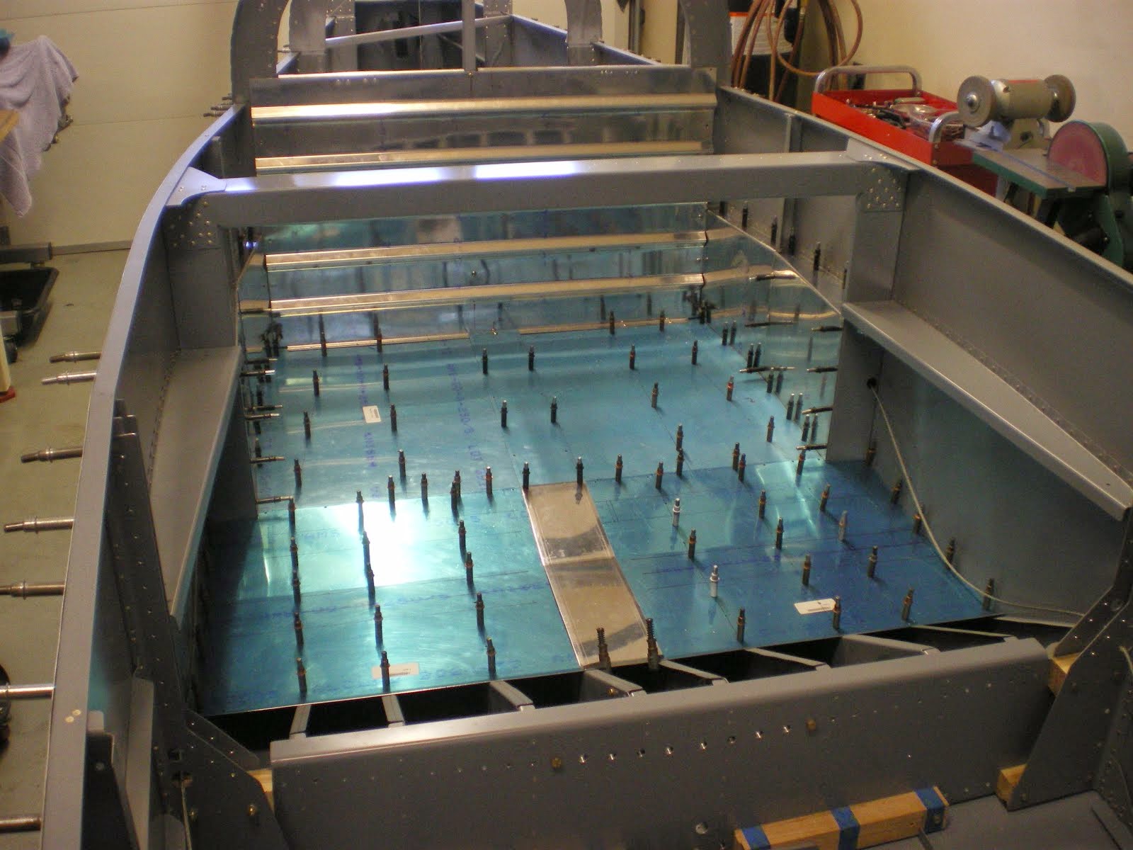
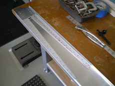
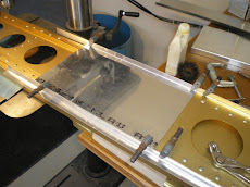
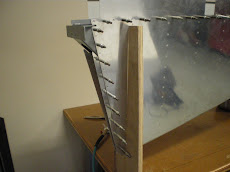
Once the jig made you assemble the skin and skeleton and slide it down into the V blockes. The spar is already drilled from the factory, you only have to drill the ribs to the skins which is where your alignment is anyways. I also used a laser plumb line during the process that shoots a line on the centerline of the V blocks and end ribs. This tells me if anything is getting out of line.
After the ribs are drilled it back apart to dimple and debur all the new holes in the ribs. Back together and then it gets riveted back together for good.
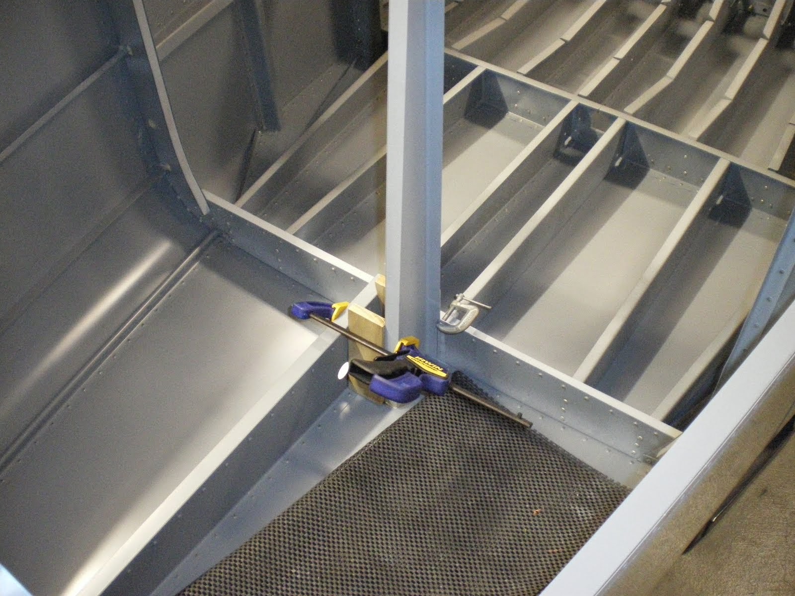
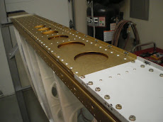
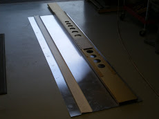
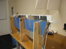
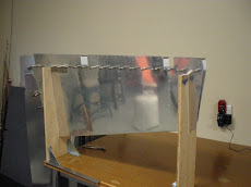
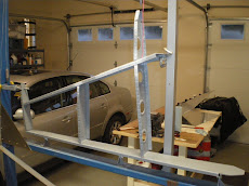
The skins come straight so you have to bend the curves to pull the two skins together at the front of the rudder so it can fit behind the vert stab spar. I use a piece of pipe and some duct tape then lay the rudder flat on the bench and clamp it down. You roll the skin onto the pipe to make the curve needed to get both side to come together in the middle. The you pop rivet this all together and this is what makes the front of the rudder.
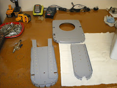
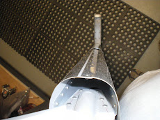
Next comes the rudder bottom with the tail light. I opted for just the position light with no strobes. My light did not lay down flat on the mount for the light so I had to build that up with epoxy and floc. I also decided to pop rivet the bottom of it instead of screw it on with nutplates. You can get the light and wiring out of it just fine without having to remove the rudder from the airplane. Cutting the fairing to fit around the rudder horn is a PITA. What I did is take some tape and taped it around the horn then pulled it up carefully then put it back down on the fairing and marked it out. I cut it out with a dremel and it fit perfectly. I wired all of the wiring for the light and then I had to put some small nuts on the inside of the light mount in the fairing. This gives you something to screw the cap into to hold the glass cover over the light. This is all at the end of the rudder tip so there is not much room to get those nuts down in there and then epoxy them in. Once this is all done, I mount the light and fairing and then do the top fairing as well.
Some time back I primed all the parts and assembled the skeleton of the rudder. I then backriveted the stiffeners to the skin. I backrivet as much as I can because it gives you a smoother skin surface overall and it all adds up to drag if your skins are not smooth.
Next comes the jigs. I found some extra plywood from a felt box down at the mill and hauled it home. 3/4" plywood makes some nice jigs. I measured the spots on the skeleton where I wanted the skin supported and then measured the skin V at each location. I then transferred this to the plywood and cut them all out using the skil saw and cut the V's in the band saw. I then squared up the edges on the disc sander so the jig would be square to the bench. I leveled my bench top and then made a centerline on the table top. I made 90 degree lines from the centerline at each jib location and them attached the jig to the table top with brackets and laser aligned the top and bottom of the V's on the jig so that there is no twist in the two V's relative to each other and everything is centerlined to the table top. It is critical that you get this right as your control surfaces will be twisted if you don't and this will make the plane fly out trim which all caused drag and loss of speed. Believe it or not some guys have reported up to a 15mph loss of speed by making things out trim. That's a lot of gas to make up the speed with extra power.
Once the jig made you assemble the skin and skeleton and slide it down into the V blockes. The spar is already drilled from the factory, you only have to drill the ribs to the skins which is where your alignment is anyways. I also used a laser plumb line during the process that shoots a line on the centerline of the V blocks and end ribs. This tells me if anything is getting out of line.
After the ribs are drilled it back apart to dimple and debur all the new holes in the ribs. Back together and then it gets riveted back together for good.
The skins come straight so you have to bend the curves to pull the two skins together at the front of the rudder so it can fit behind the vert stab spar. I use a piece of pipe and some duct tape then lay the rudder flat on the bench and clamp it down. You roll the skin onto the pipe to make the curve needed to get both side to come together in the middle. The you pop rivet this all together and this is what makes the front of the rudder.
Next comes the rudder bottom with the tail light. I opted for just the position light with no strobes. My light did not lay down flat on the mount for the light so I had to build that up with epoxy and floc. I also decided to pop rivet the bottom of it instead of screw it on with nutplates. You can get the light and wiring out of it just fine without having to remove the rudder from the airplane. Cutting the fairing to fit around the rudder horn is a PITA. What I did is take some tape and taped it around the horn then pulled it up carefully then put it back down on the fairing and marked it out. I cut it out with a dremel and it fit perfectly. I wired all of the wiring for the light and then I had to put some small nuts on the inside of the light mount in the fairing. This gives you something to screw the cap into to hold the glass cover over the light. This is all at the end of the rudder tip so there is not much room to get those nuts down in there and then epoxy them in. Once this is all done, I mount the light and fairing and then do the top fairing as well.
Subscribe to:
Posts (Atom)


.JPG)