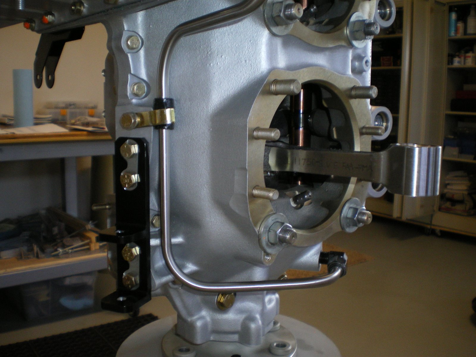
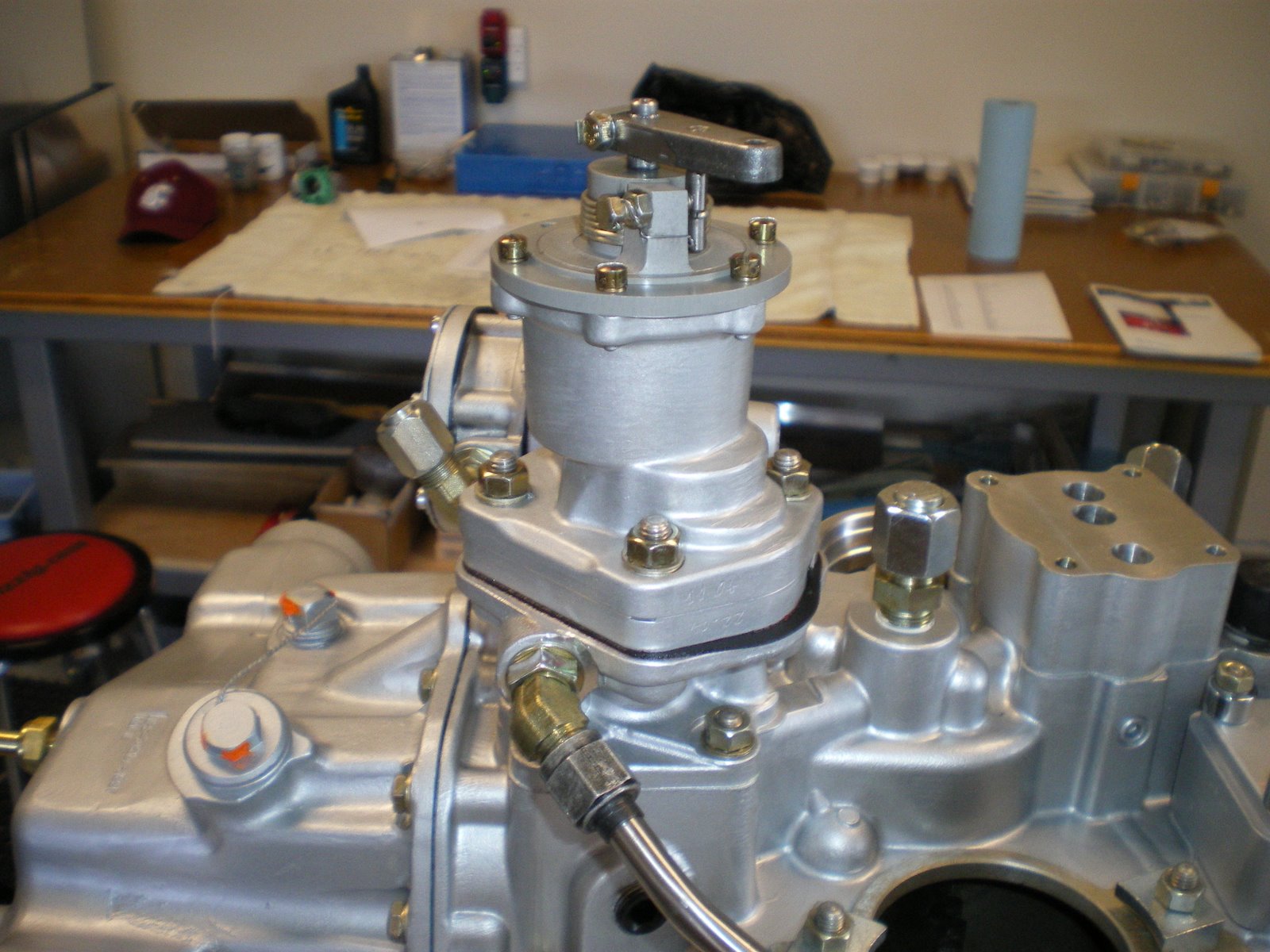
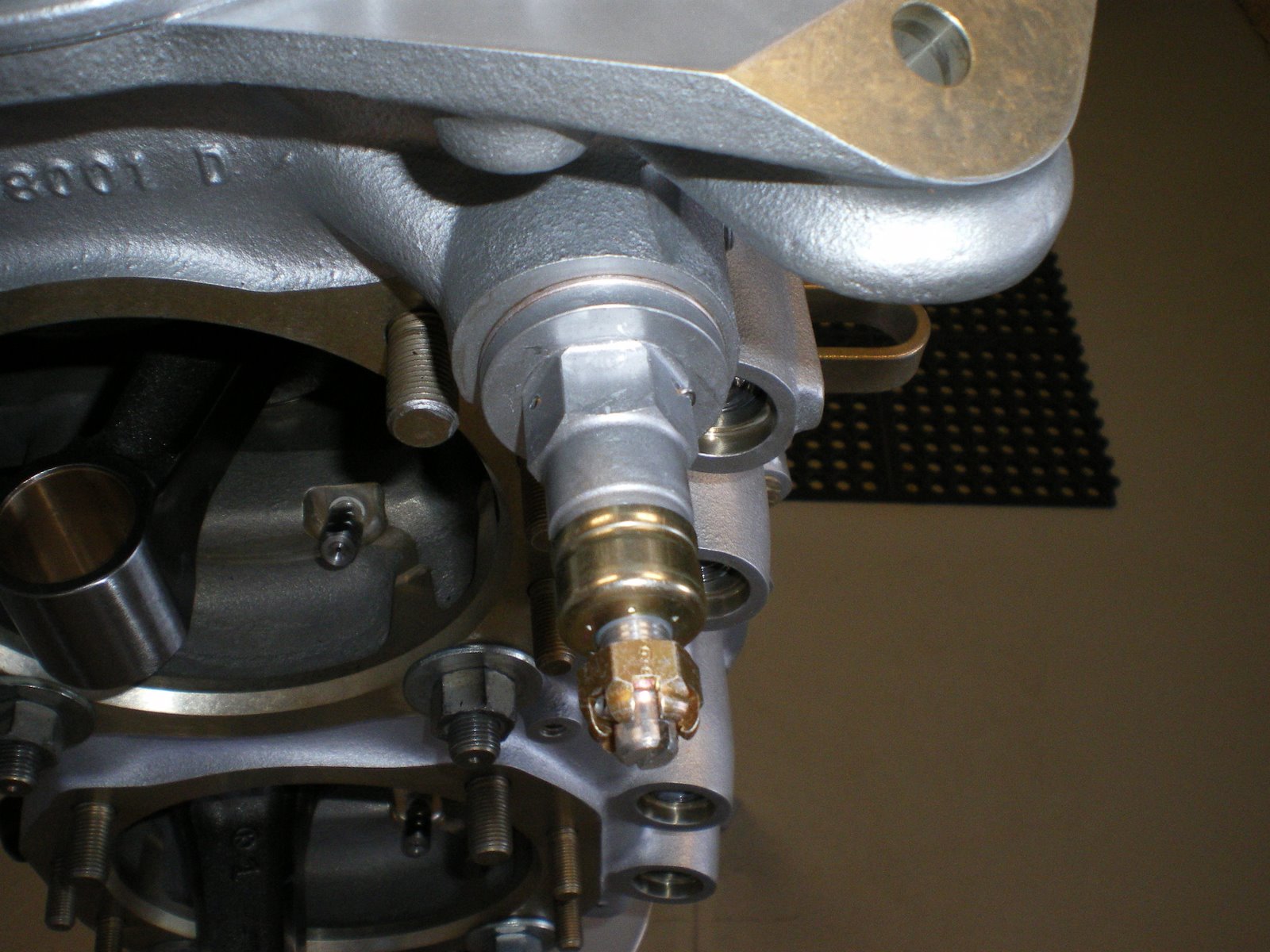
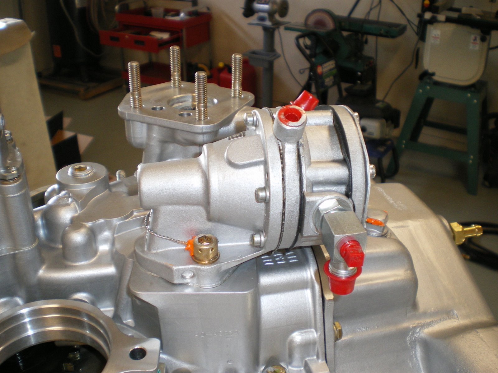
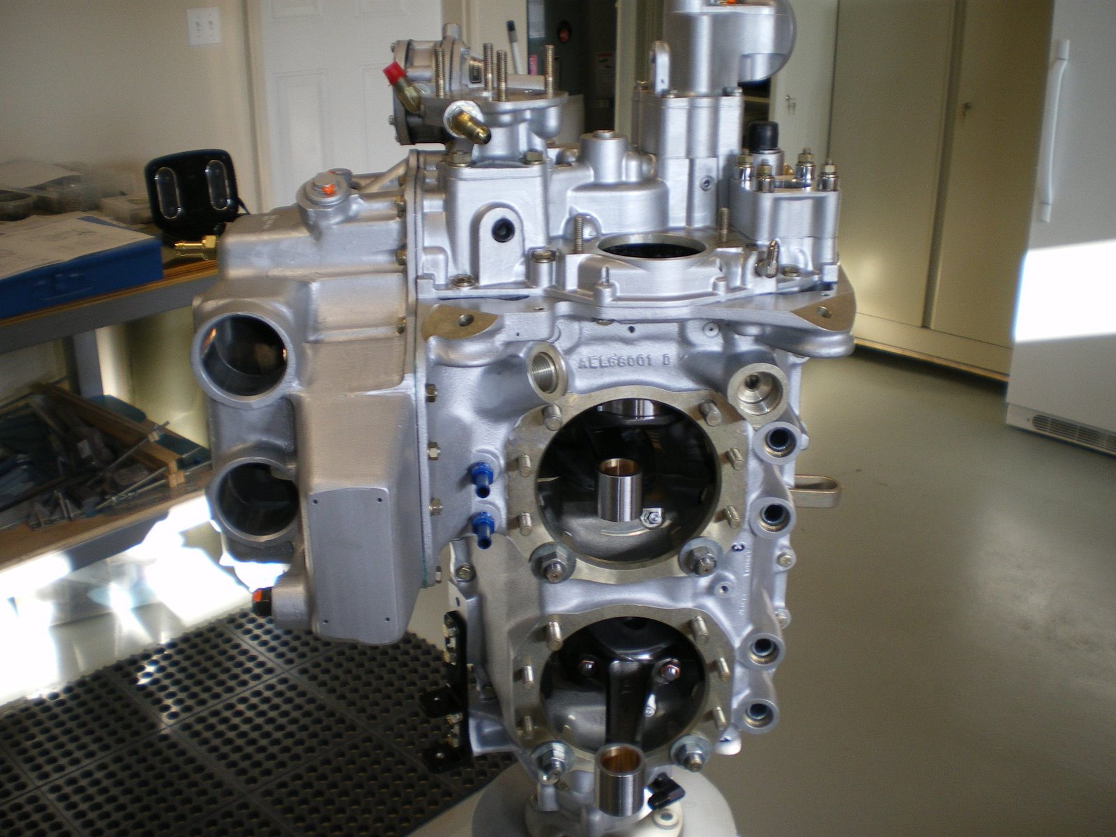
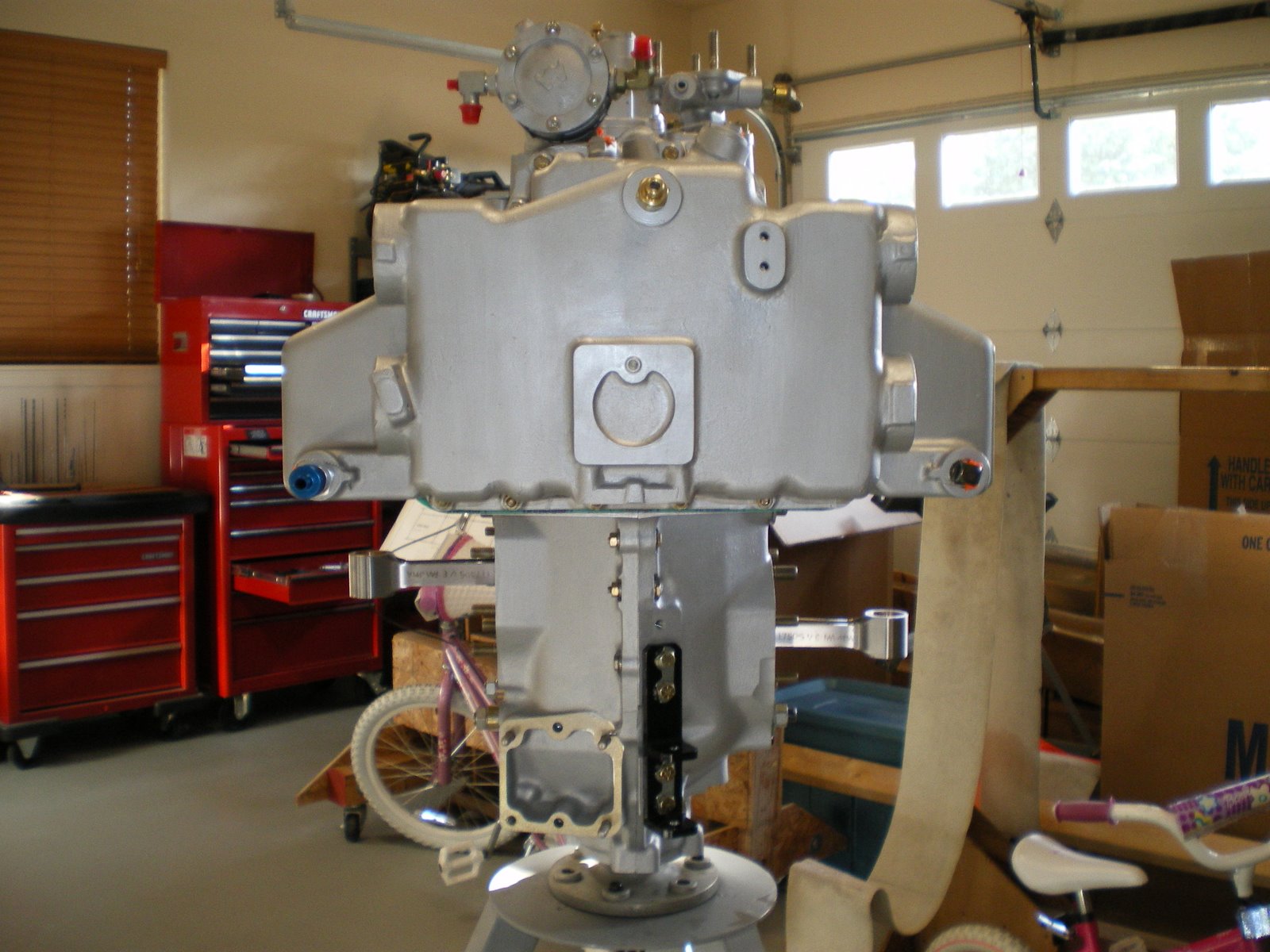
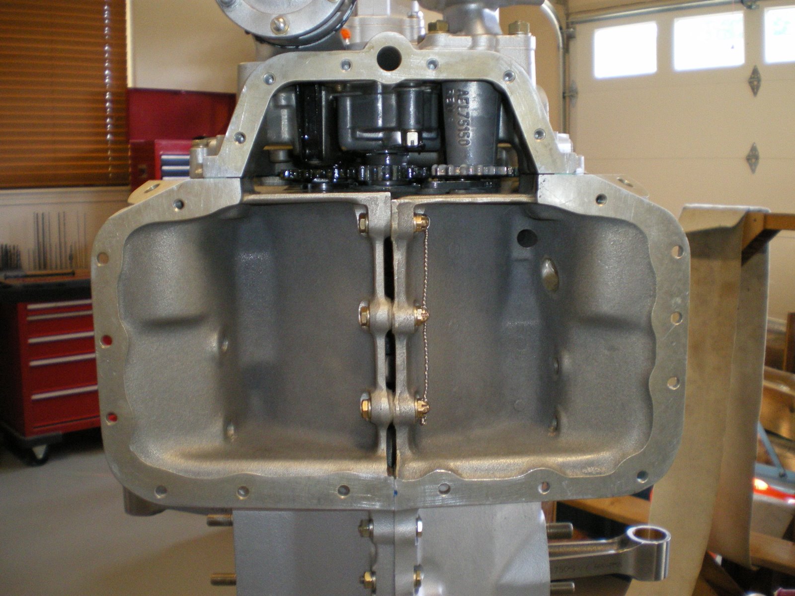
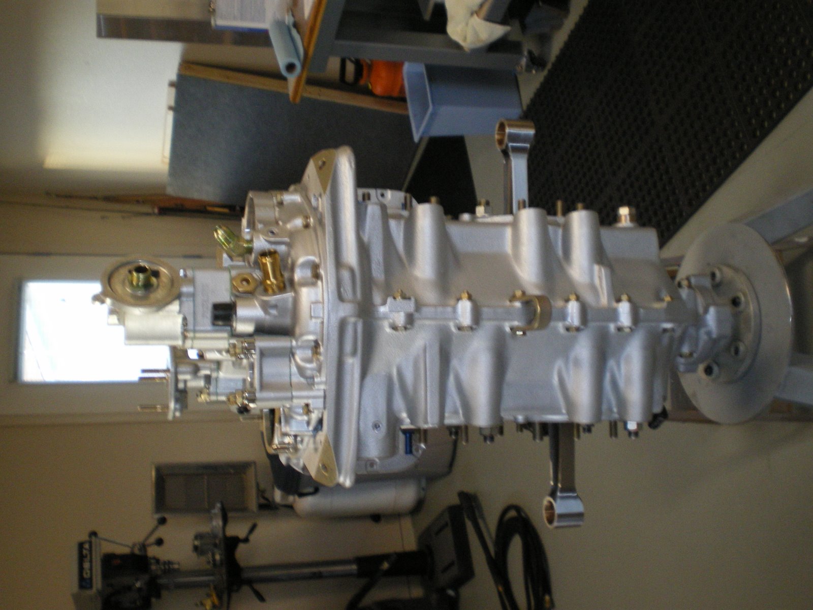
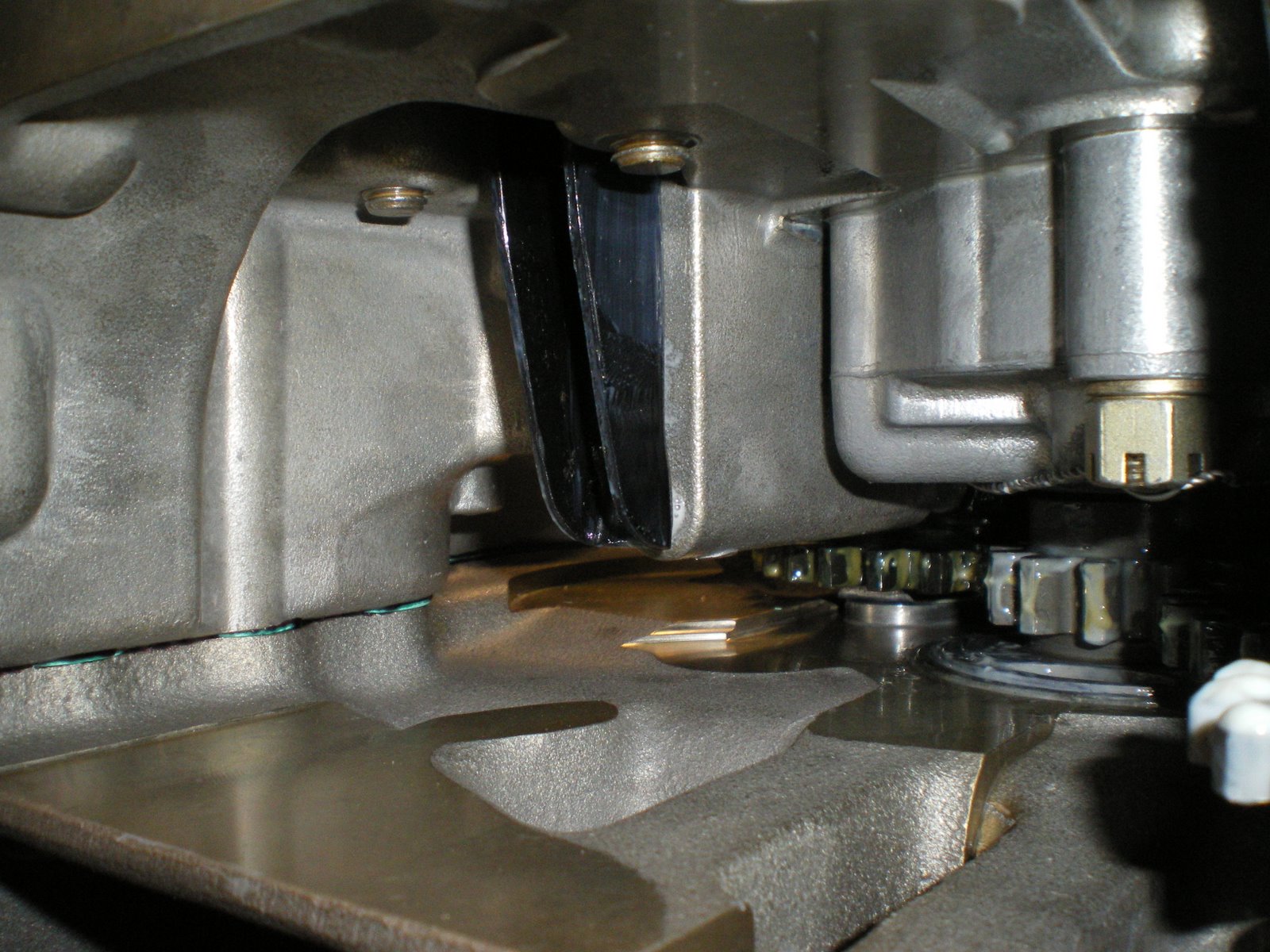
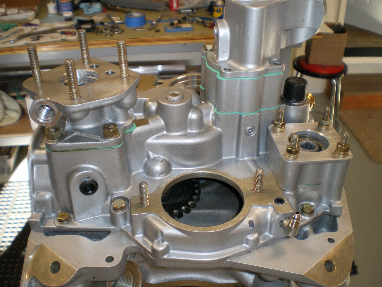
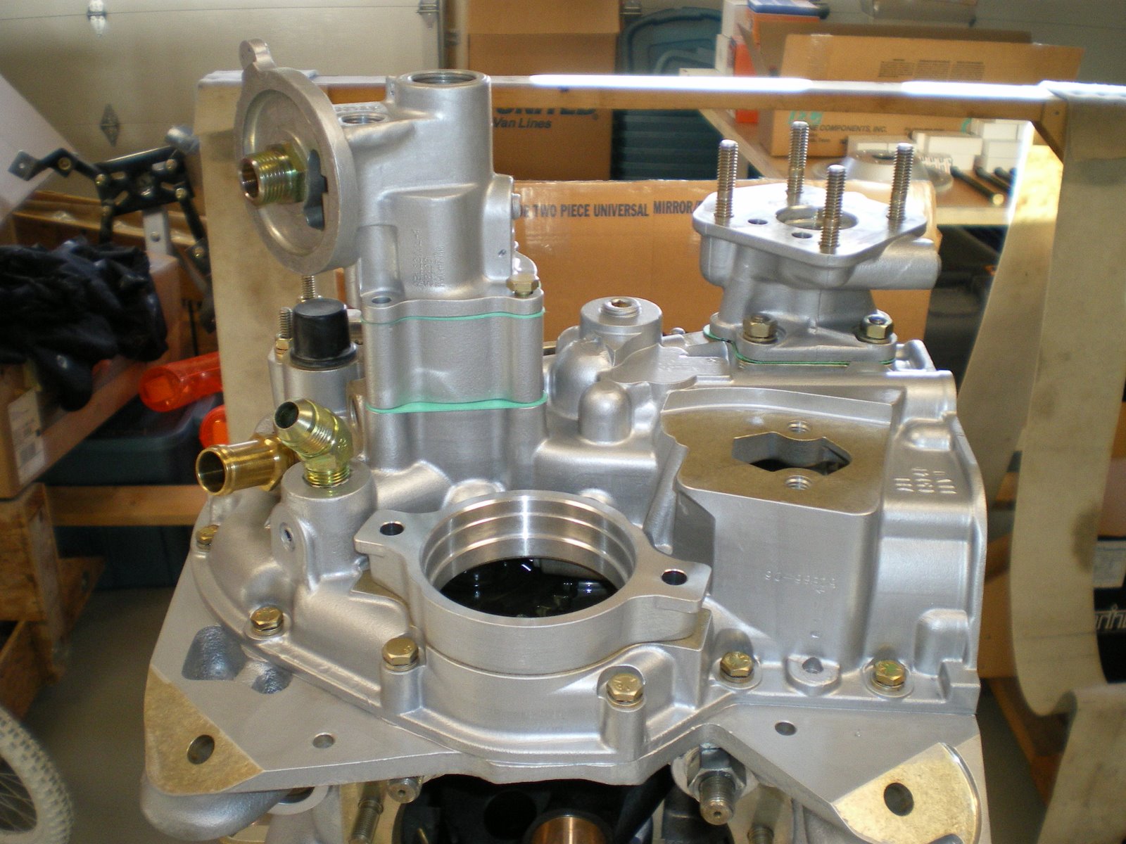
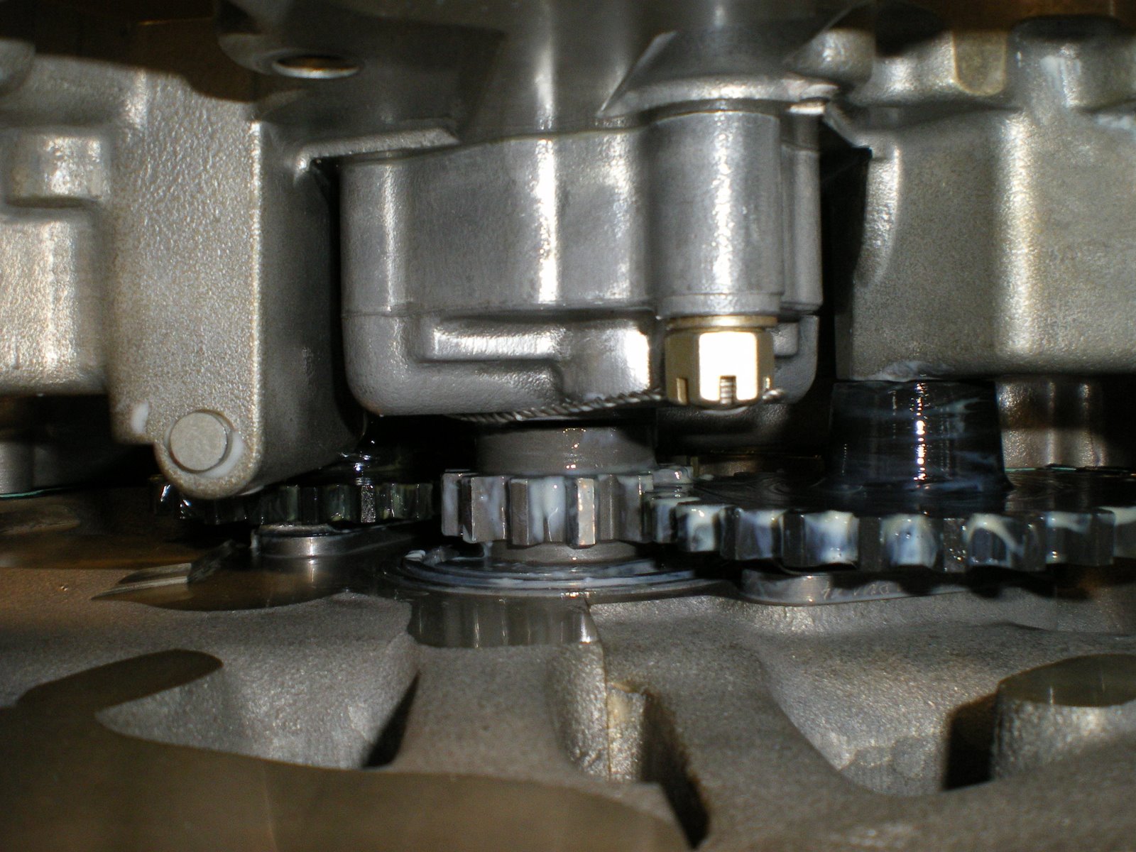
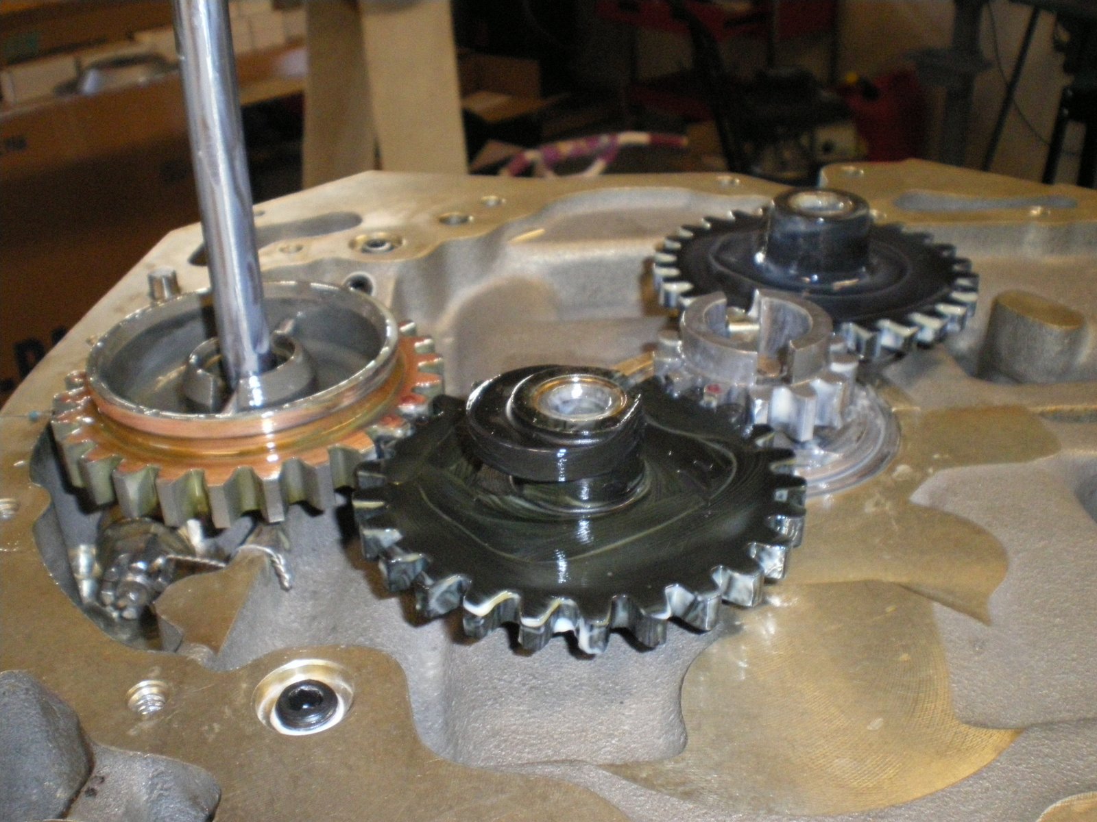
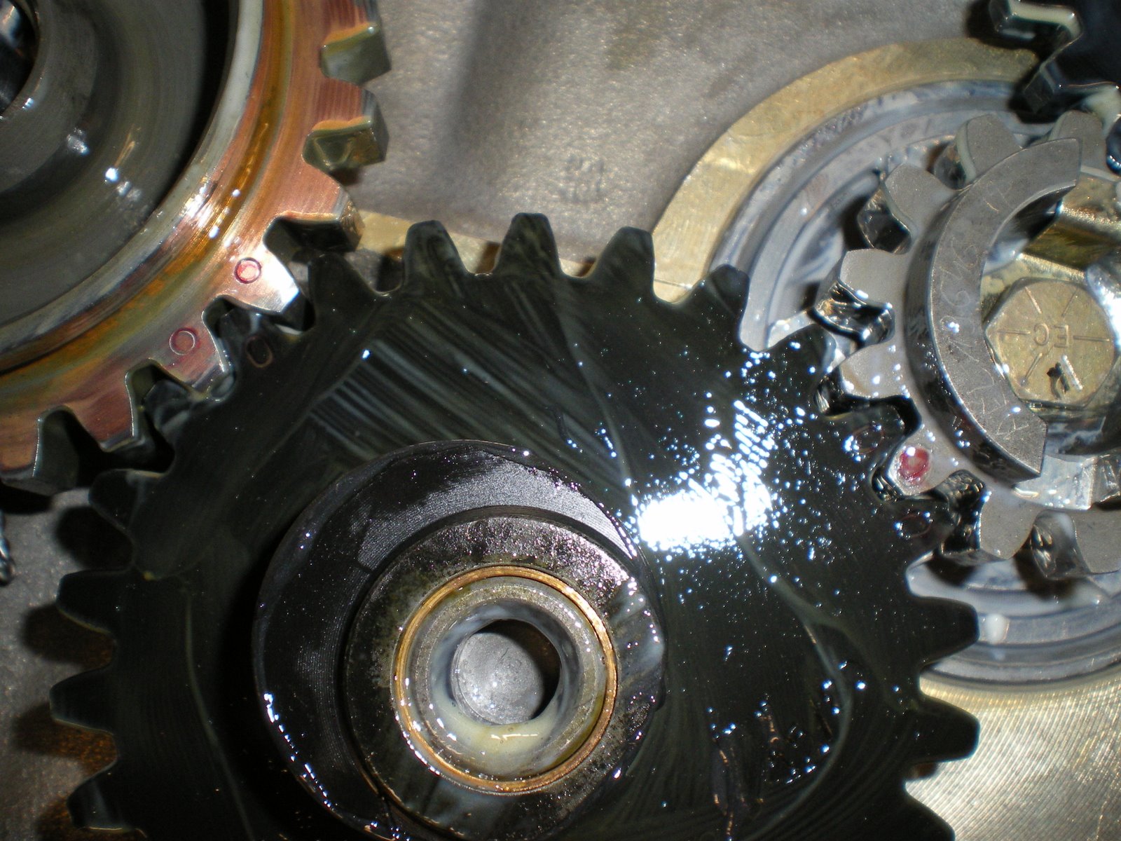
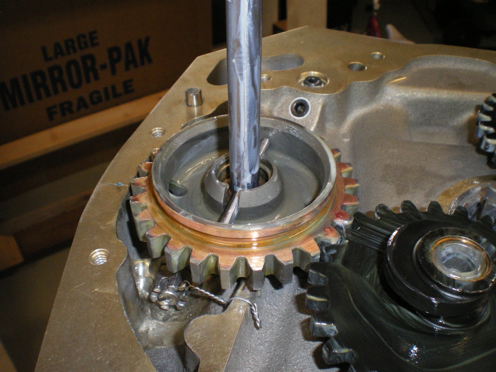
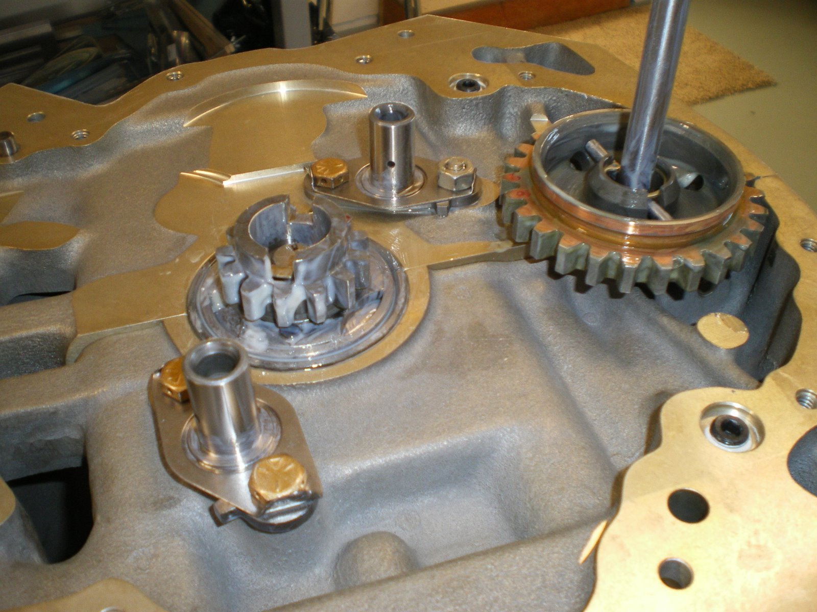
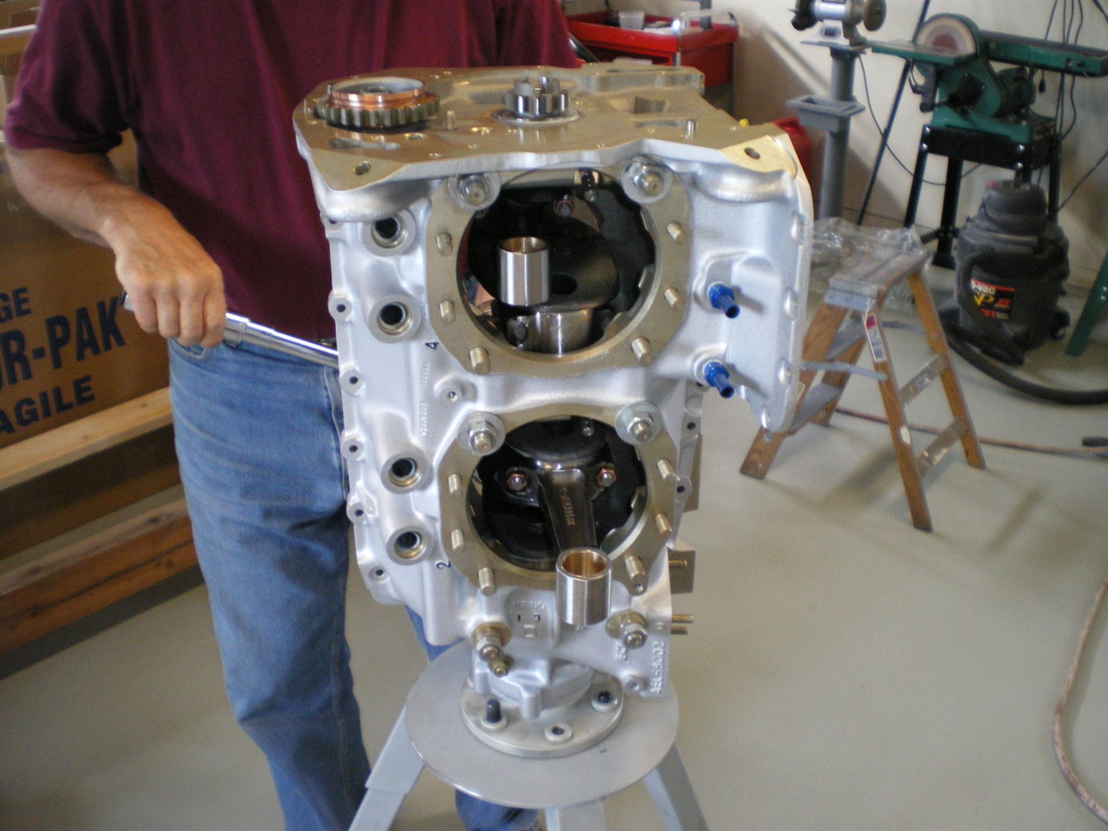
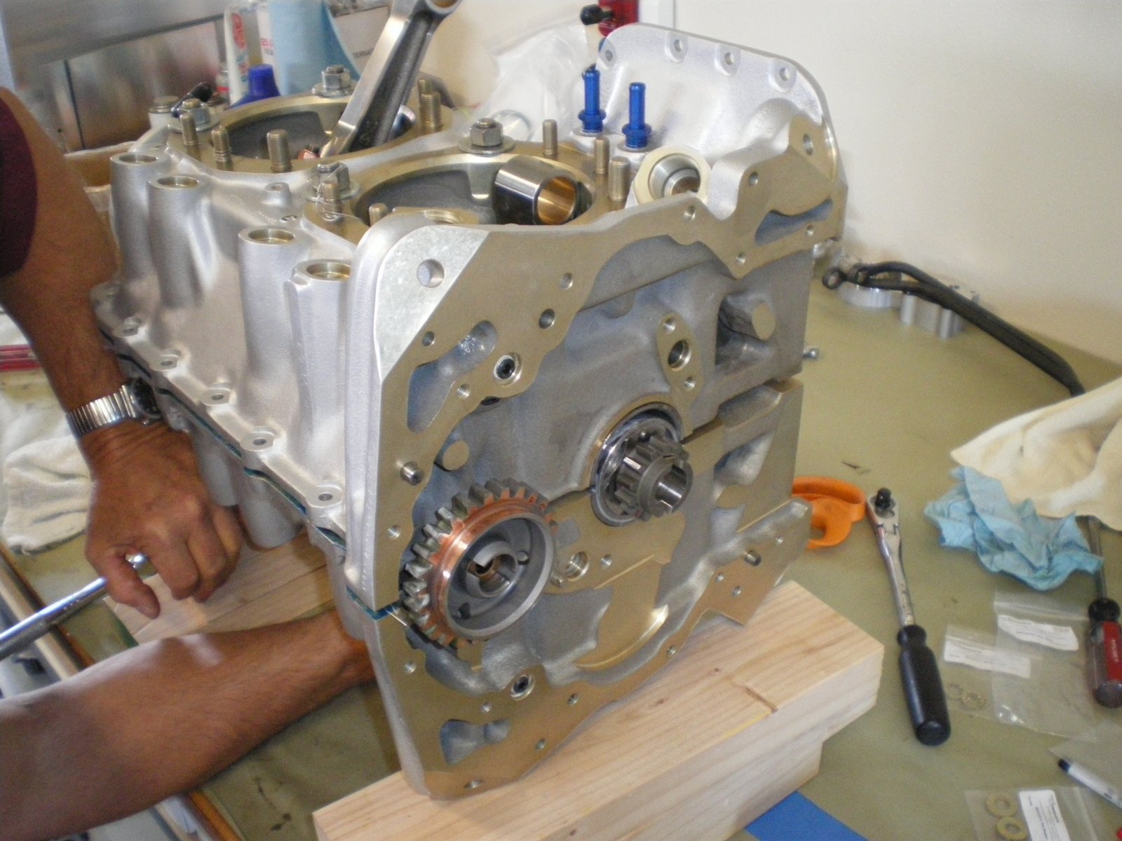
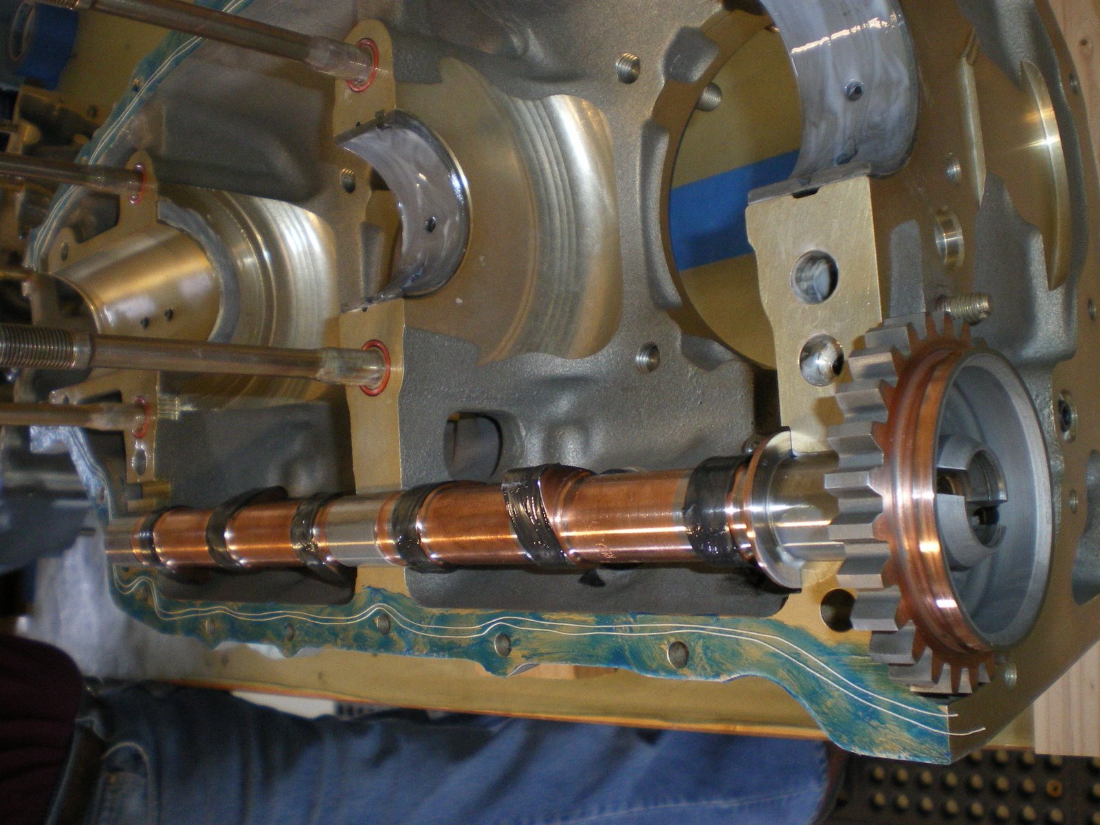
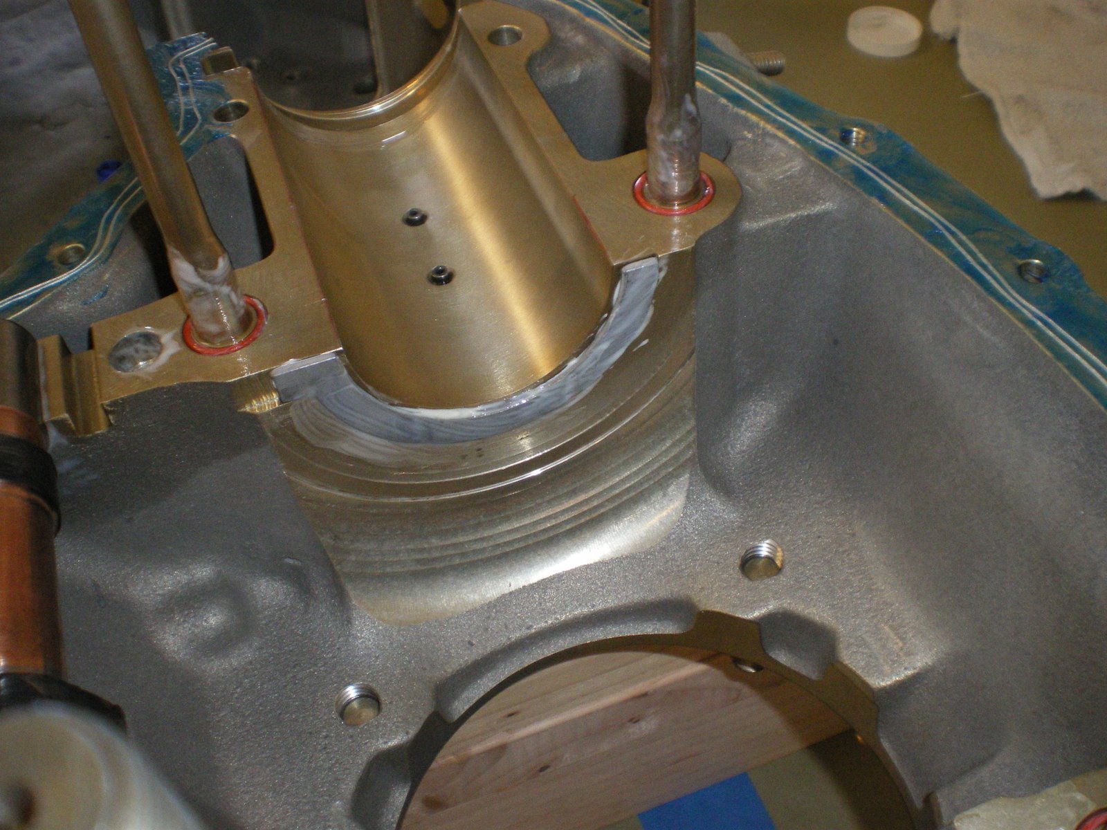
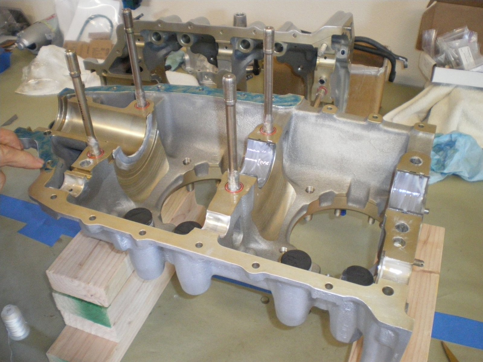
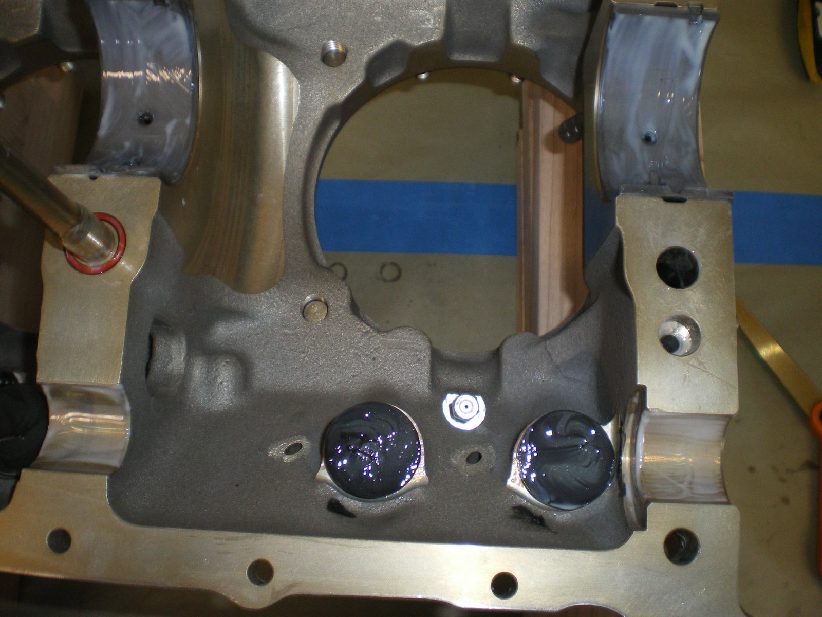
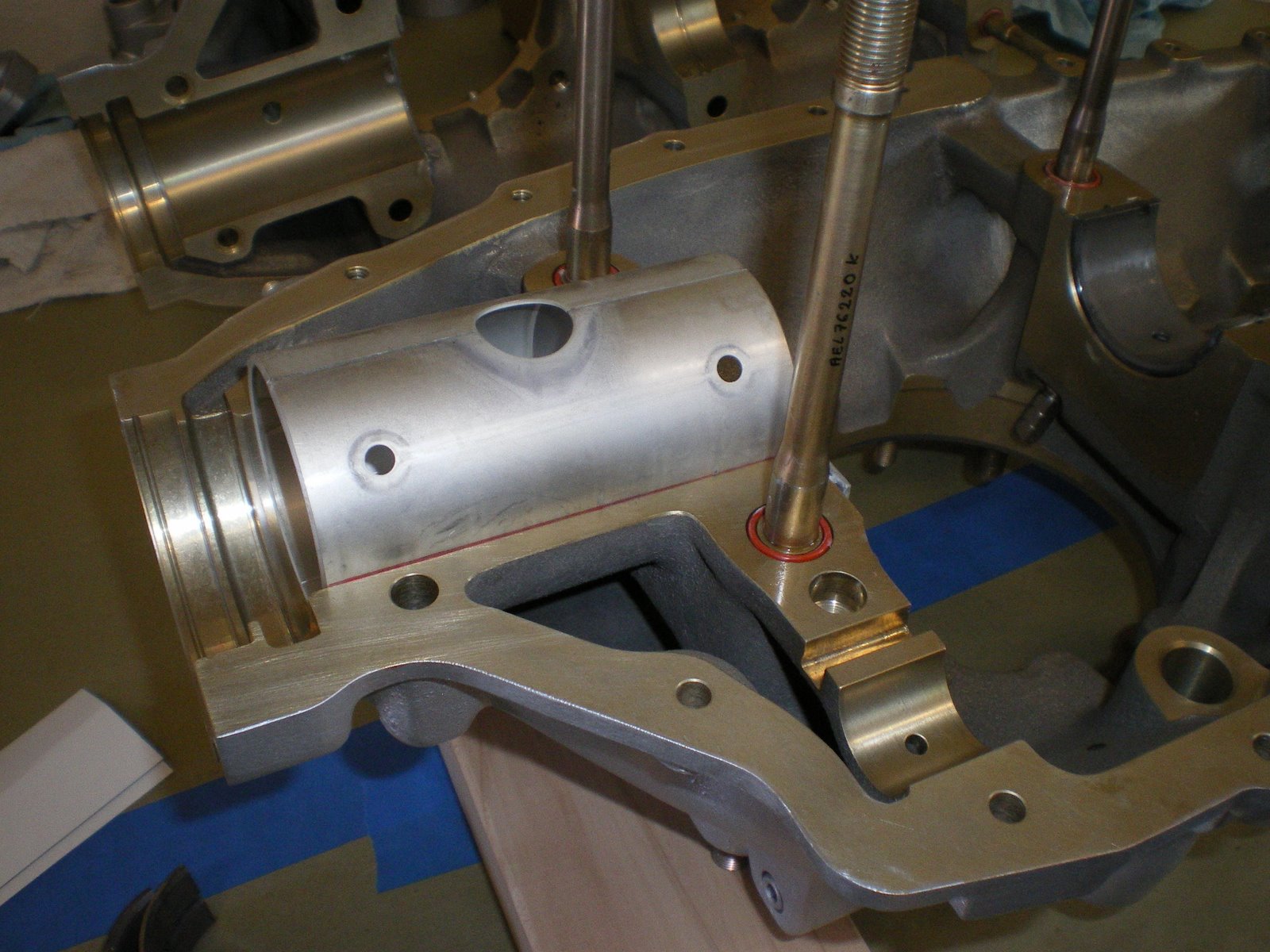
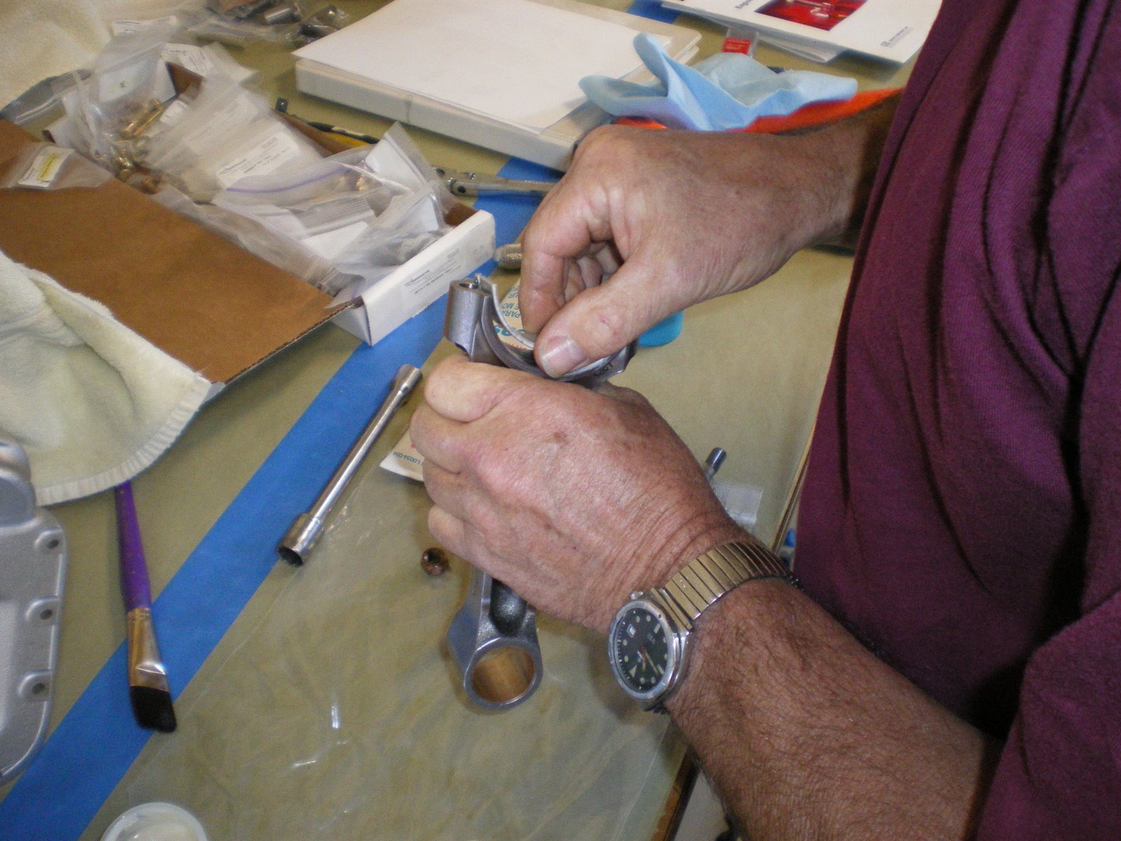
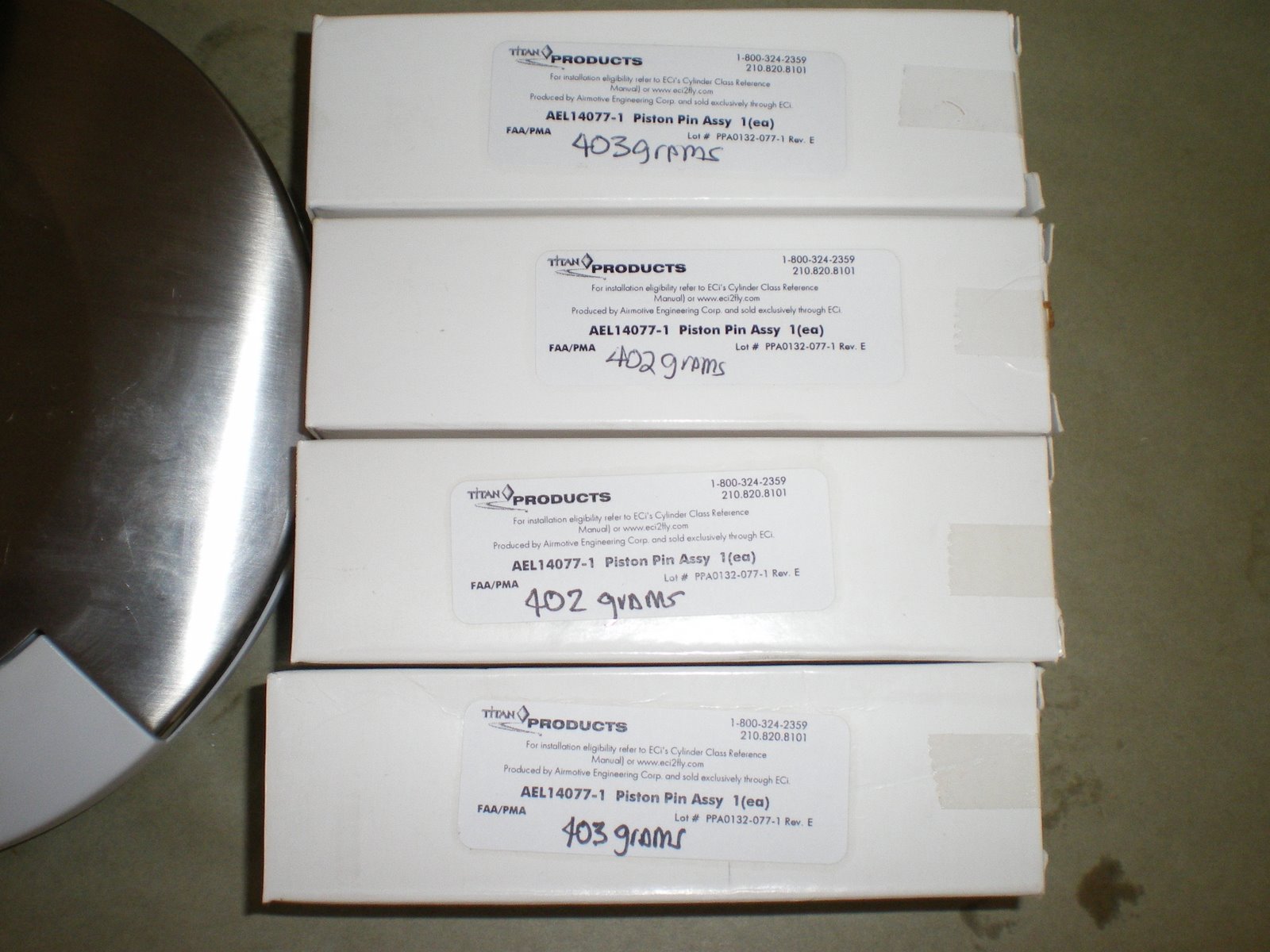
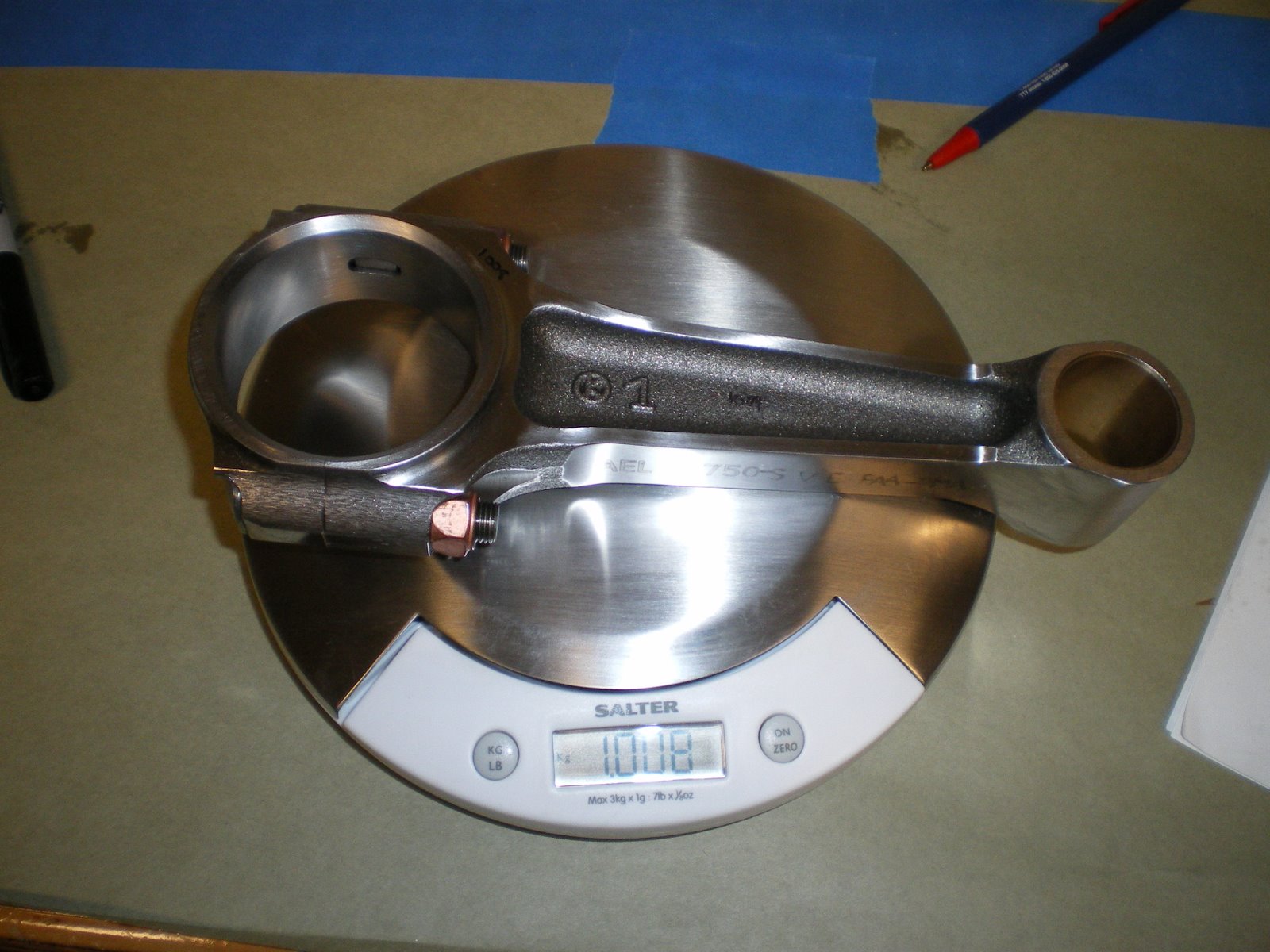
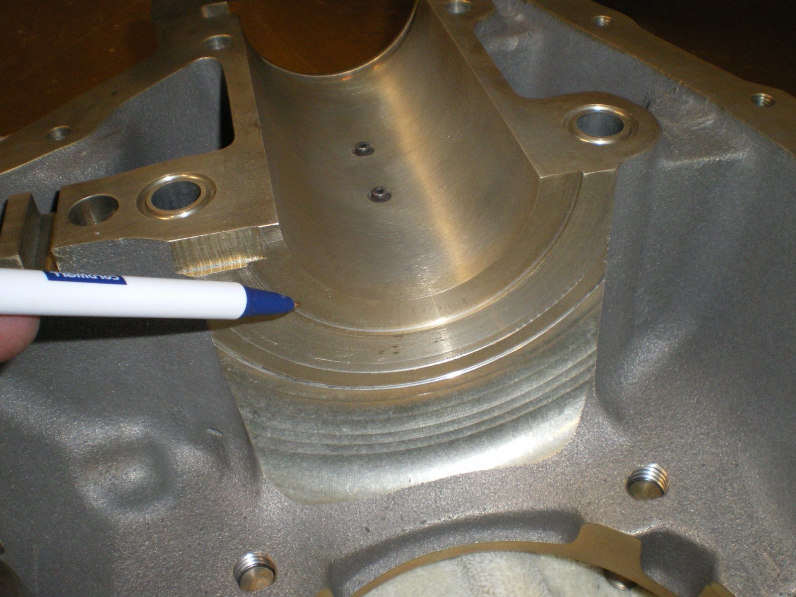
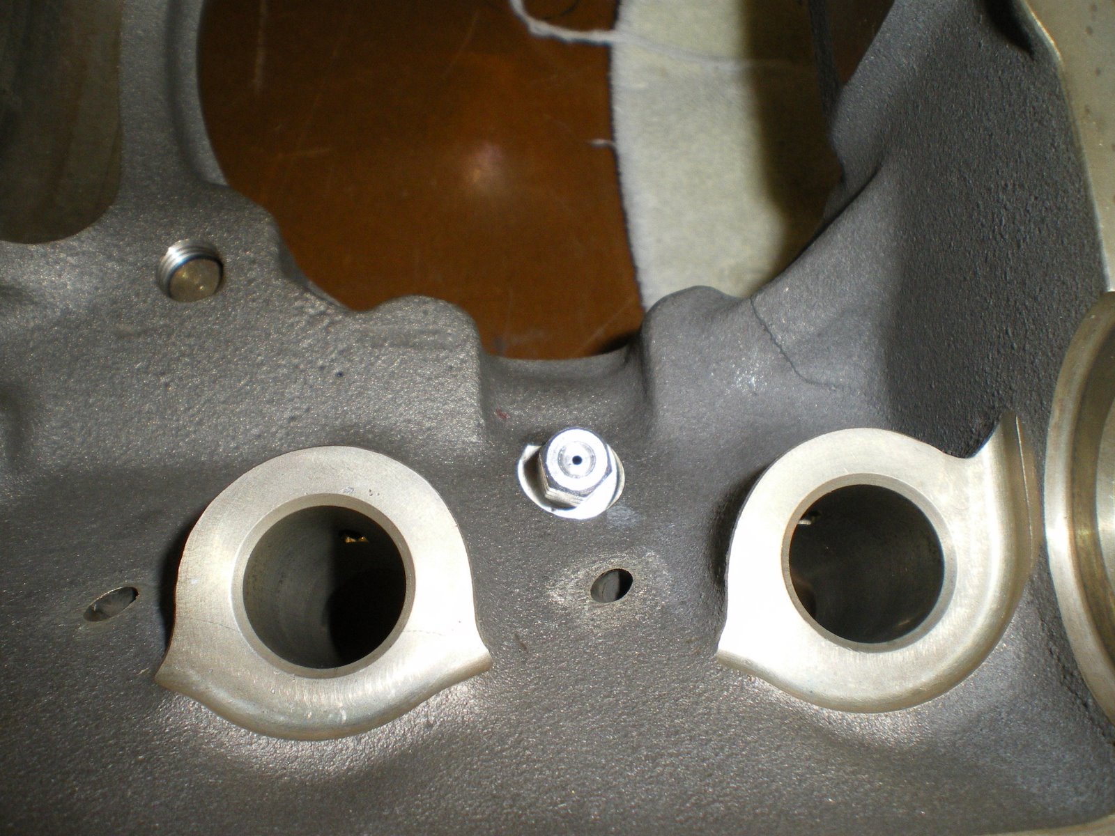
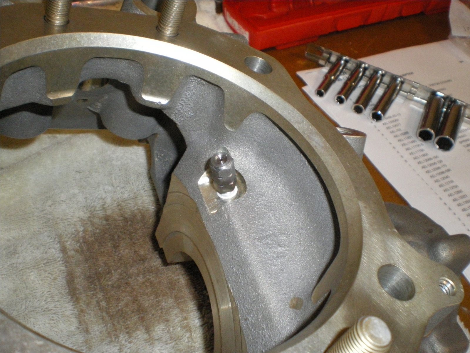
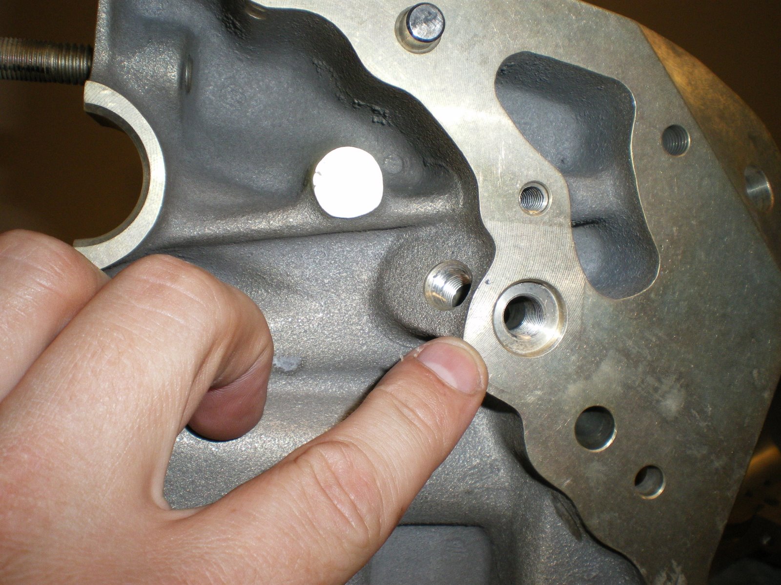
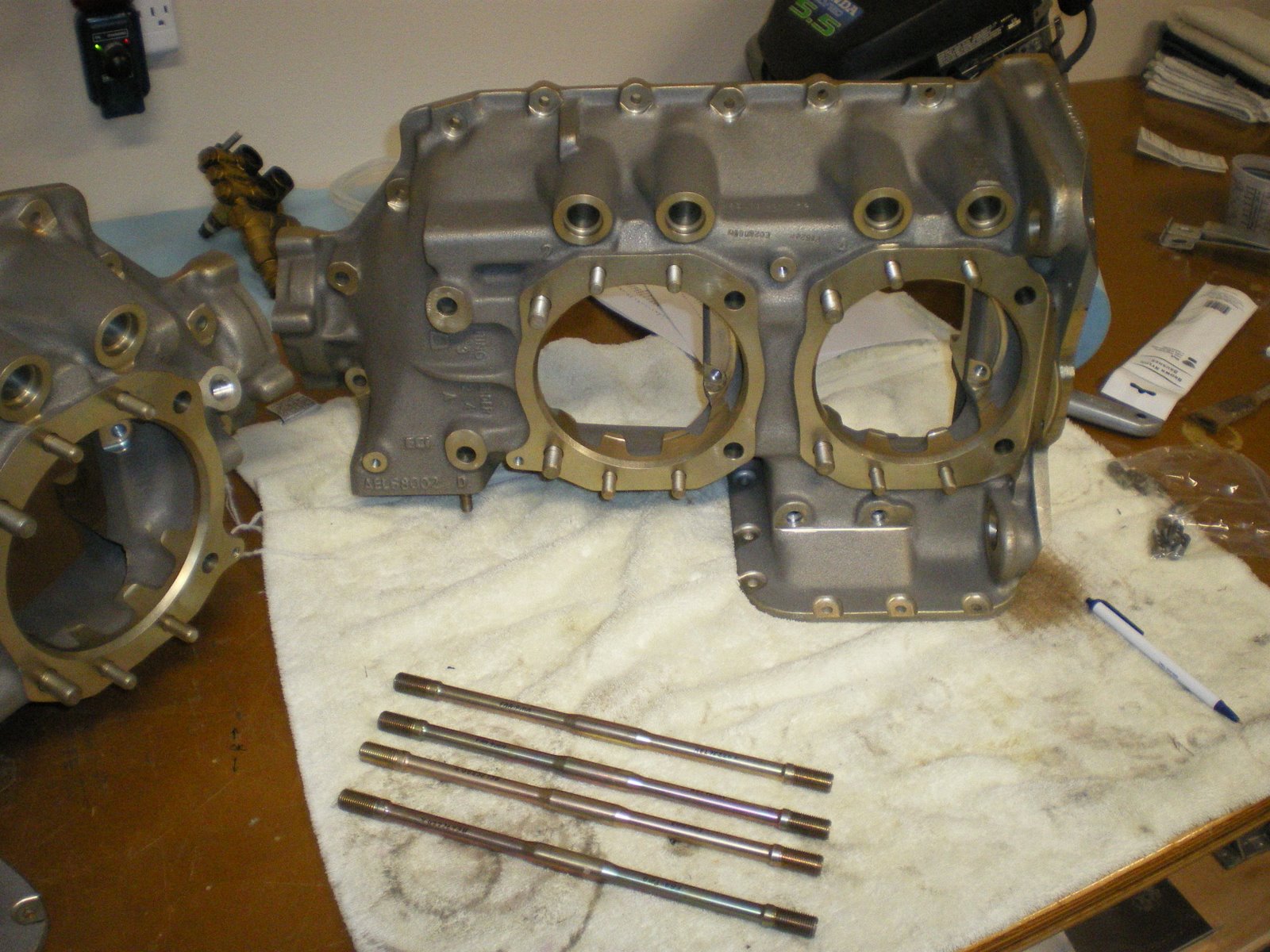
I was reading through the ECi supplements and I came across one for the oil pump body. It says that the little hole on the side of the pump needs to be plugged up if you don't have fuel pump gears to lubricate. For the life of me, I cannot remember if I checked that or not. I took pics of the pump but only when it was mounted on the assy case and safetied wired. So I decided to take the assy case of and double check. It only took about a half hour to get the parts off the assy case and sump off. I double checked the pump and there was no hole at all so I was in the clear. Now I am telling you all of this because this is a lesson in learning to build engines. I would rather spend a half day pulling apart my engine to double check something just to be sure than spend the rest of my life dead because I have my pride. Swallow your pride and get out the wrenches. My family will be flying with me and I need to have that confidence that I did everything right. I put all of the parts back on the engine and I have peace of mind. I also read through all of there bulletins and checked to make sure there was nothing else that I missed.
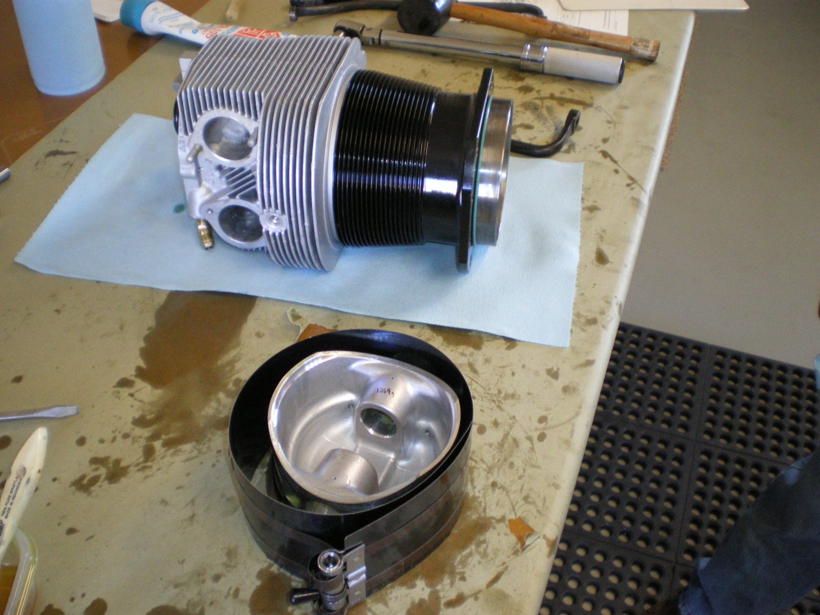
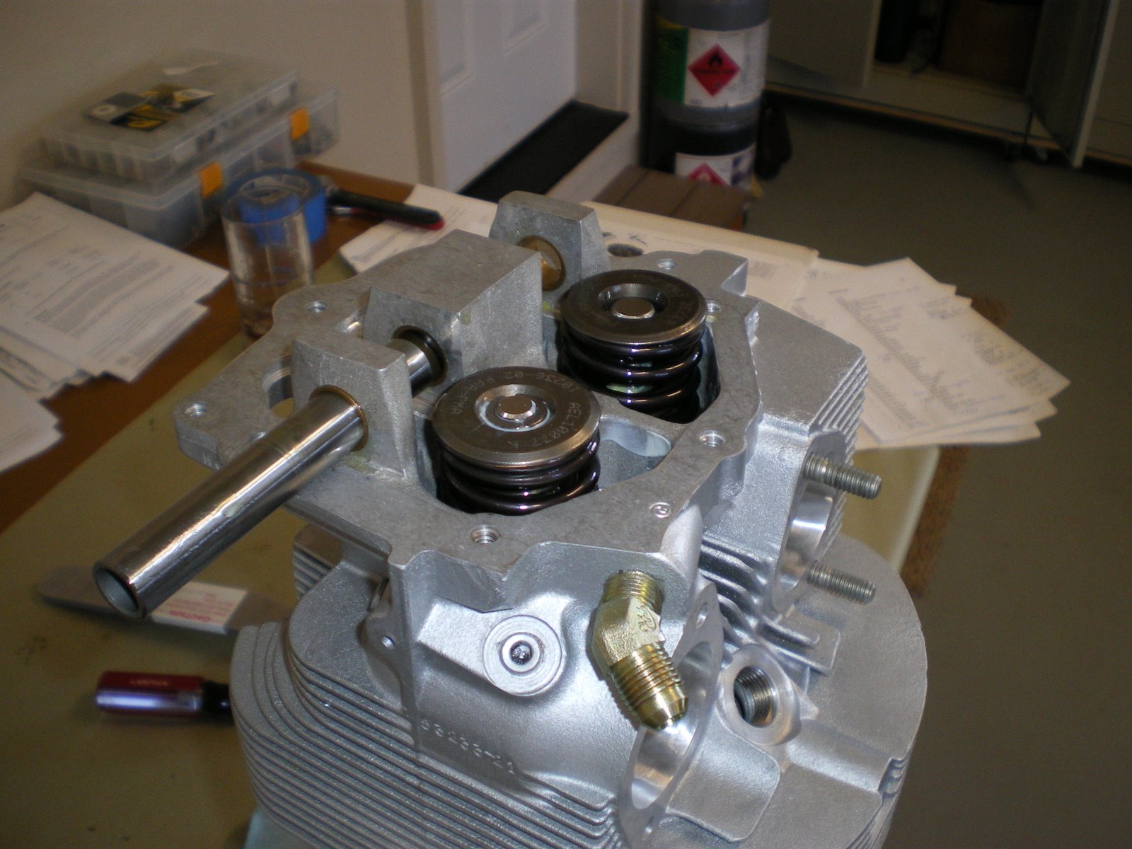
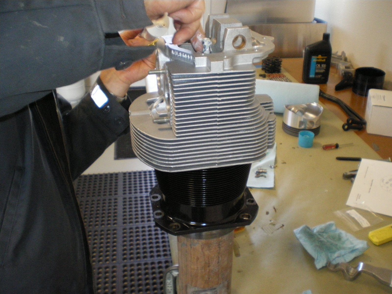
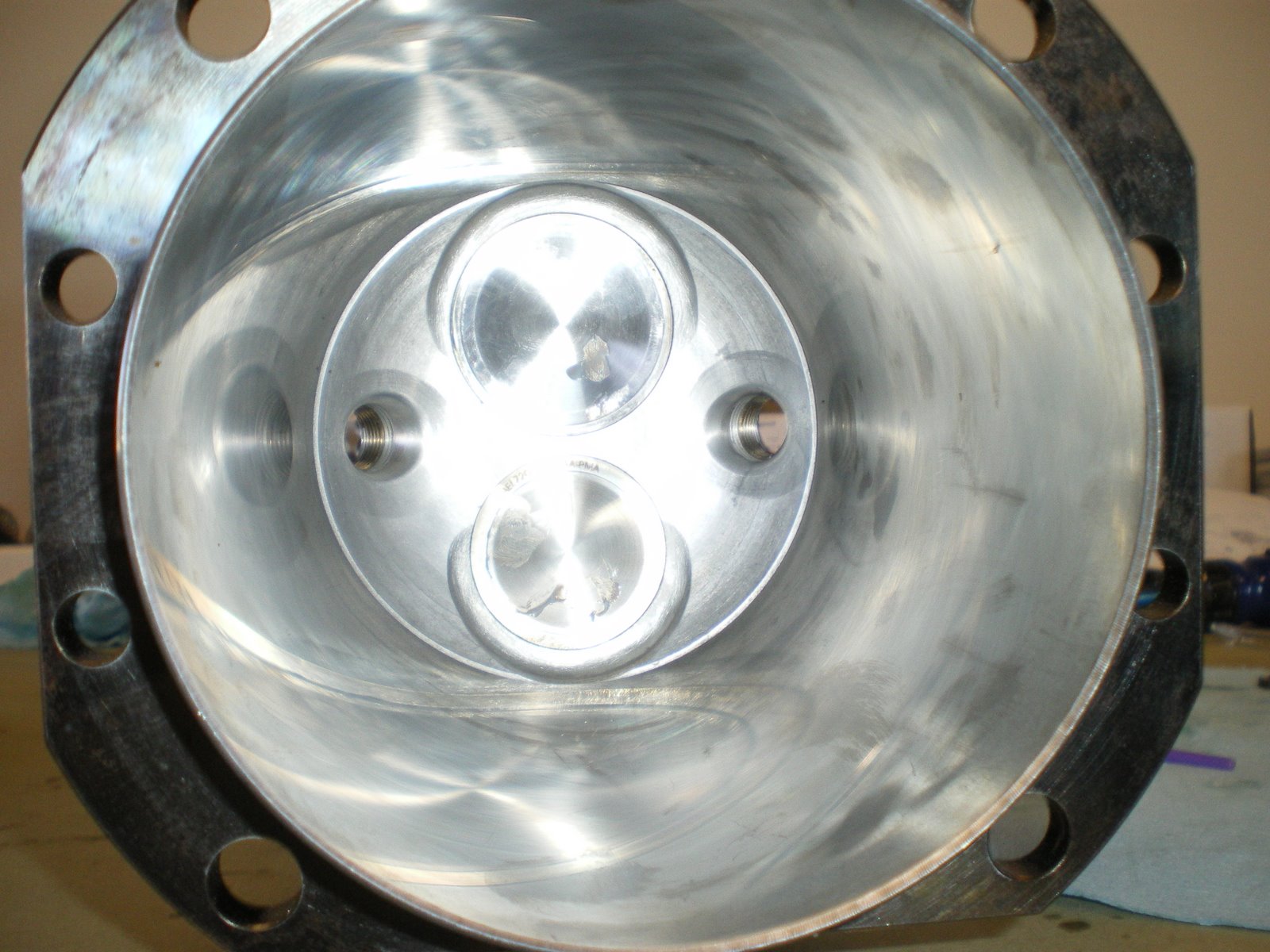
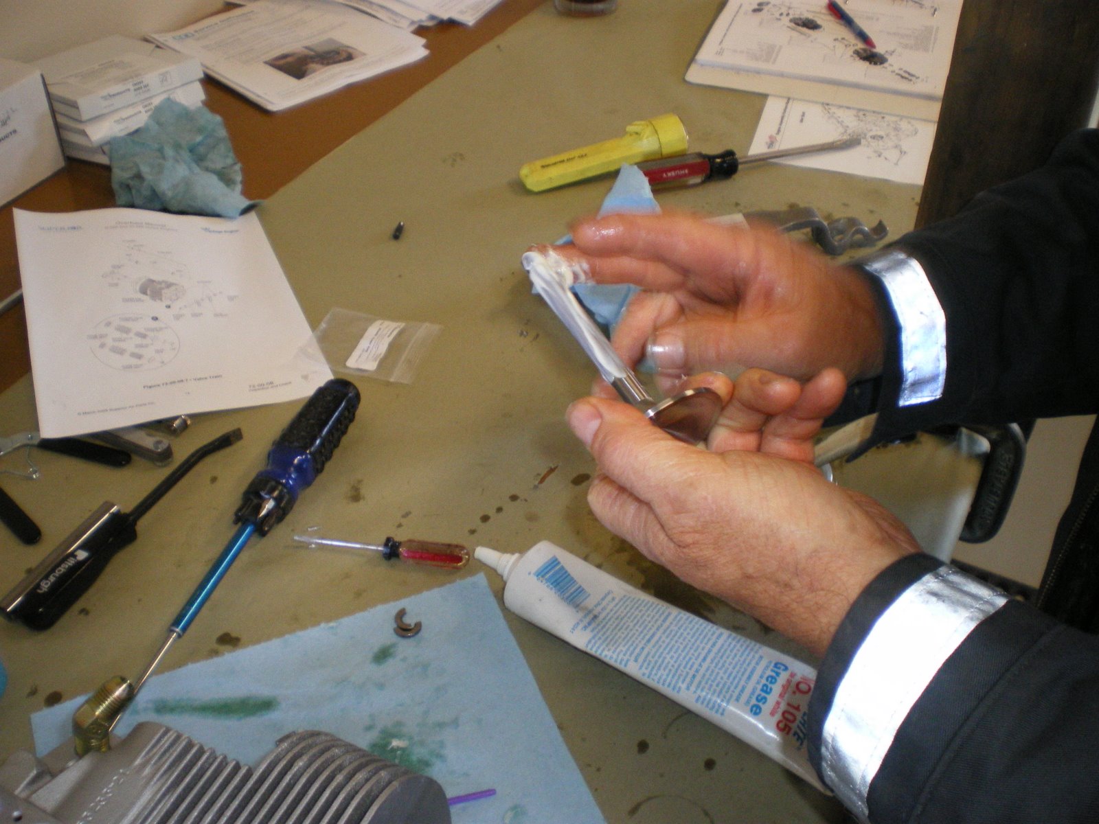
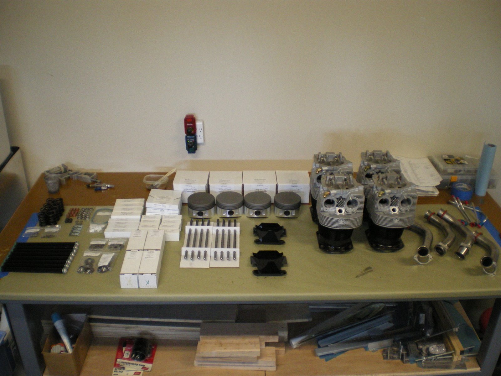
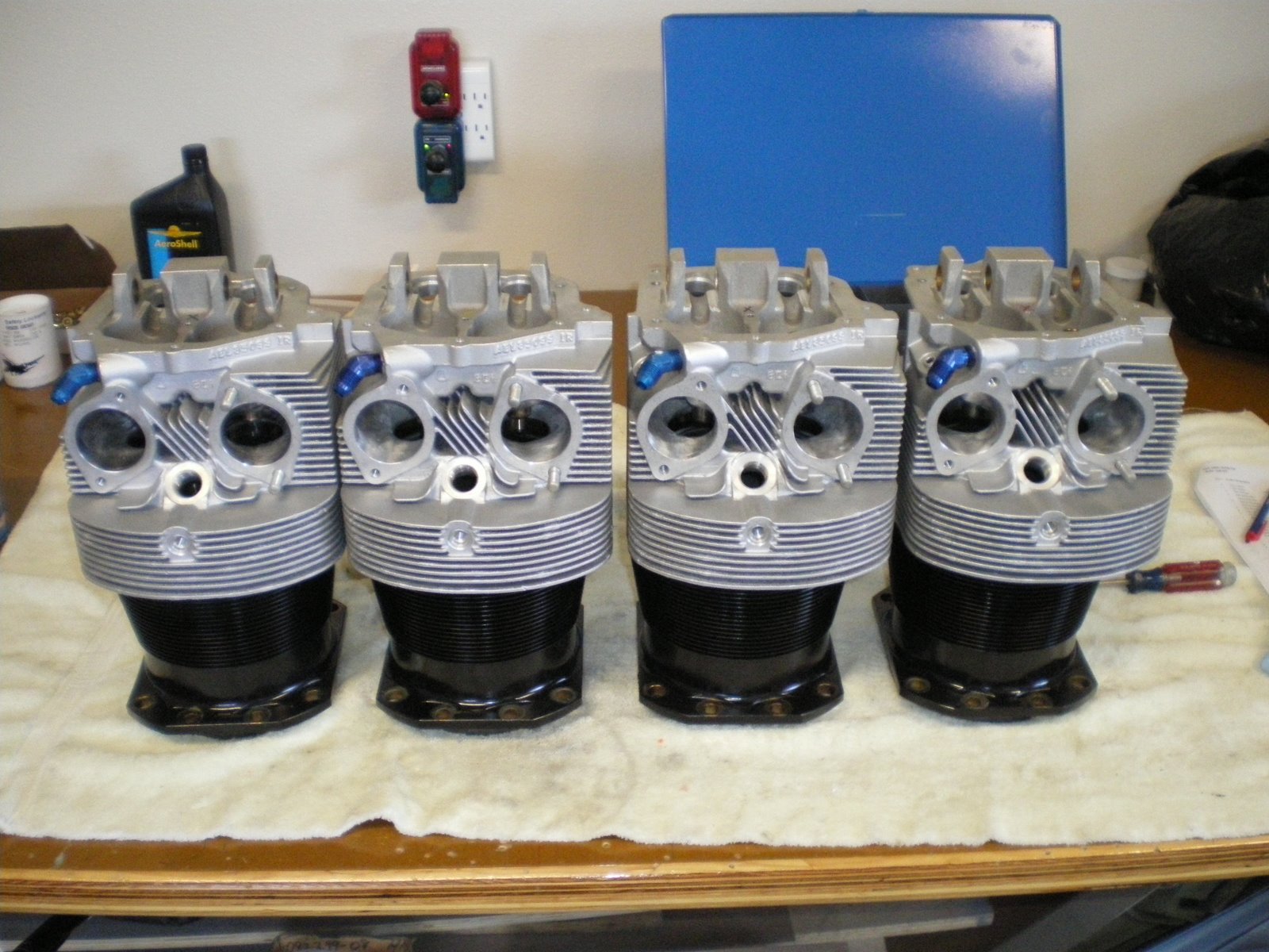
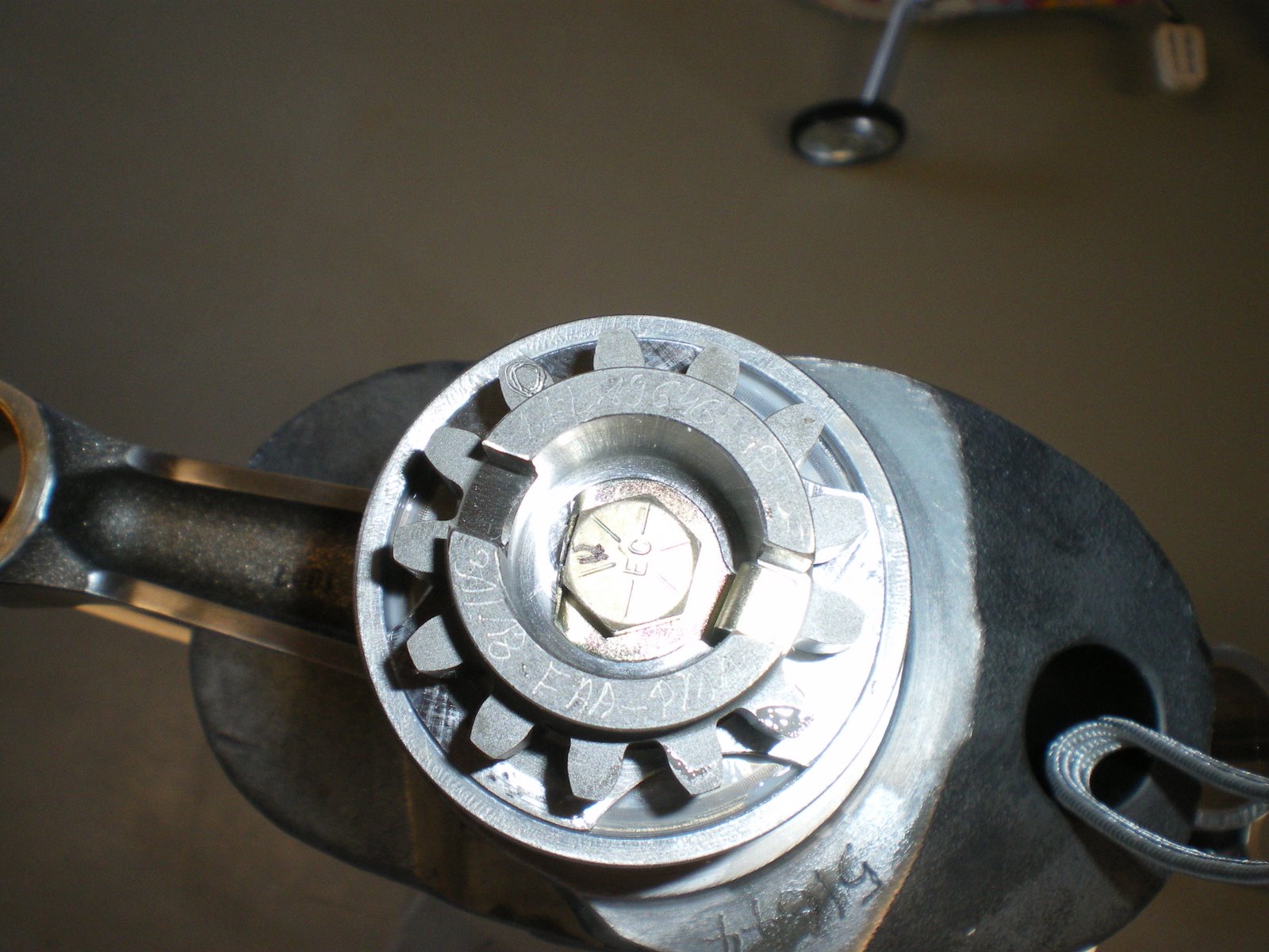
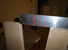
I am still waiting on my spring compressor to arrive and small flap wheel so I can finish polishing those ports in the hard to reach areas. I also am trying to figure out how the valve springs go on the cylinder heads. There is a inner and outter valve spring and there is a top and bottom to the spring itself. It's very hard to tell, but they said the double coil is supposed to go towards the bottom. Now maybe I am not seeing this but there is not double coil. The only difference I can see is that one of the sides is not as tapered down as the other. Called ECI and sent a picture so they could inform me which way it goes. They seem to be very helpful and are working on it as I write this blog. I will get back and let you know what is going on. A picture is posted to let you decide what is up and what is down.
Monday, July 28, 2008


Thursday, July 24, 2008
Fitting all of the fittings--Son of a #@%&$
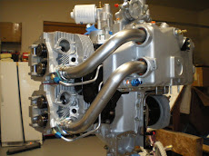
Part of the fun of putting together your own engine is finding out what does not want to fit. I am working on the oil cooler bypass fittings and the tach drive. I used the oil cooler bypass fittings before in my other RV-6. It's a special banjo fitting with special seal washers to seal the two sides of the banjo fitting. There are several reasons to use this style of fitting. One is that is can be rotated 360 degrees. So making oil lines fit up to it is very easy. The other is keeping all of the fittings up near to the top of the engine where they can be seen. The other oil line plug is down between the mags and is a little harder to get it. Plus it's more oil line to route and weighs more. The downside to using the banjo fitting is that it's a special thread 5/8-16. They is a special Cessna fitting that can be purcahsed if you don't mind paying 150 bucks for it. I have gotten surplus fittings from the days of old from Jesse at AERO. I cannot use the fitting since it's too close to the oil filter housing. The 90 degree oil filter solves one problem but creates another. I also have an issue with the Van's Tach that I am trying to use. I got the kind for the engine that is for ones without vacuum pumps. I will have to get one for ones with vacuum pumps that is a cable and mounts on the firewall. I had this on my last airplane and it works. It's just one more thing to mount of the firewall. I have also installed the new oil line fitting that goes in between the mags. I will use this one (as most others do as well) to supply oil to my cooler. I have also installed the 5/16 studs for the fuel injection servo on the sump. Studs are used here becasue there is no room for bolts. I have also finished polishing my ports on the cylinder heads for now. I am waiting for some smaller flap wheels to come in so I can get in there in the tight places. I will try and post some pics of the problems I face tomorrow.
Wednesday, July 23, 2008
Putting the mag gears on.
I tried to install one of the mag gears on the mag that has the impulse coupling on it. I took off the nut and went to put on the gear when the impulse coupling came up and unwound a couple of turns. This thing is spring loaded and there is a correct number of convolutions to keep the exact amount of tension on the impulse coupling. A quick call to my Dad and he had a overhaul book for Slick mags. I will get this from him when he comes up to help me get the cylinders on. Trying to get the gears torqued down while keeping them from spinning is going to be hard. There is a pin that comes with the mag but that is to hold the mag gear from moving after you have it timed and are installing it into the engine. It is not sturdy enough for me to torque it. More to follow.
Working on the cylinders
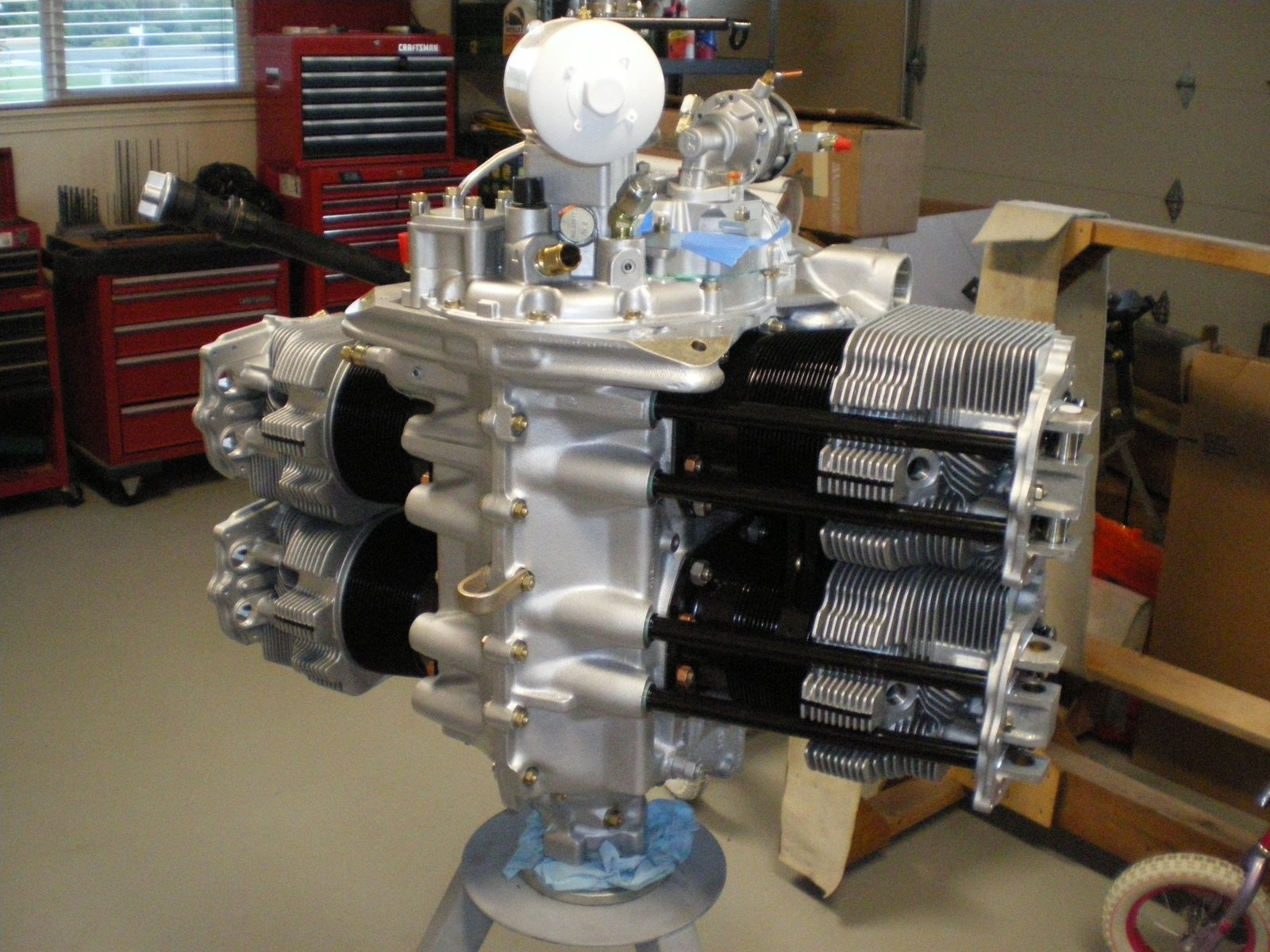
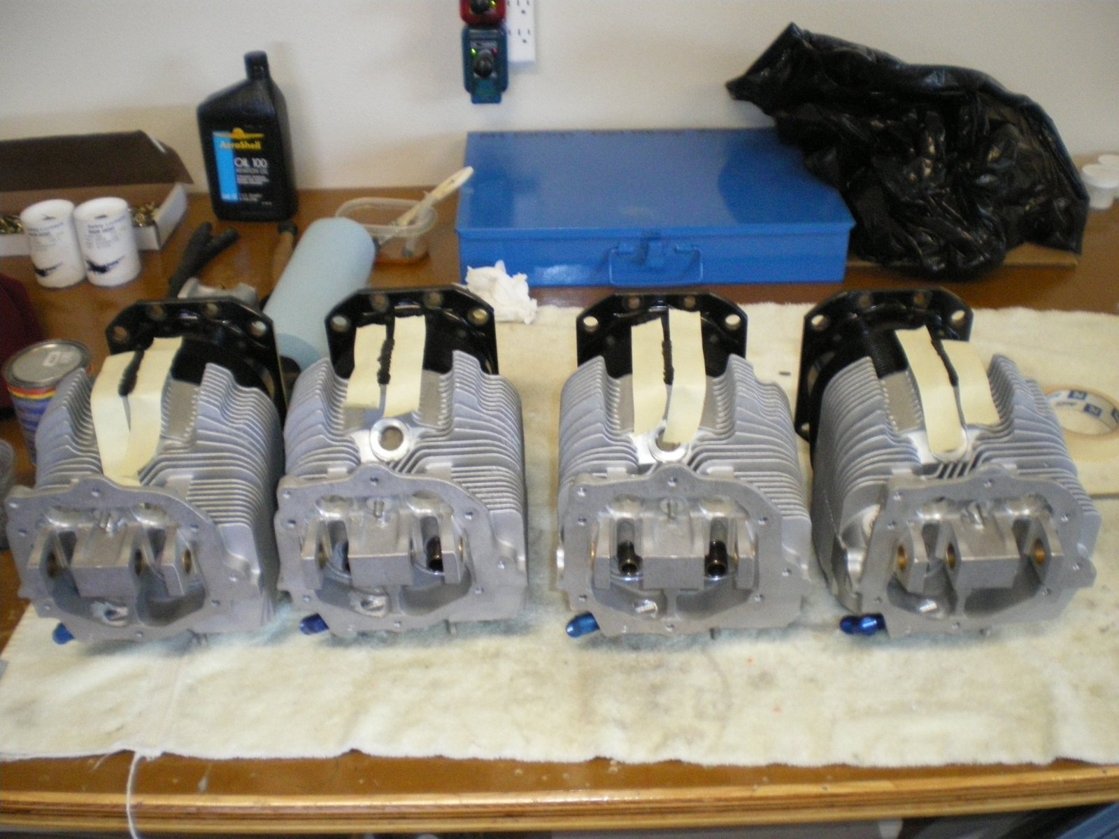
I started working on the cylinders. I have painted the top aluminum heads silver. I used the 3M cup system to spray the cylinders so that I could paint upside down. It worked ok but the paint came out in blotches. I had to take a brush and brush out the heavy spots. I thinned the paint down with reducer but it was not enough. It says 20% but it should be more like 30% and use a fast reducer.
After the top was painted I started on the bottom. Having problems with the top I had the local paint shop put some of my enamel in a spray can. They take my paint and put it in a spray can. It already has the solvents in it and it makes clean up a snap. I masked off the top and the lower portions so paint would not get on then and then took the cylinders outside and spray each one individually. They came out nice.
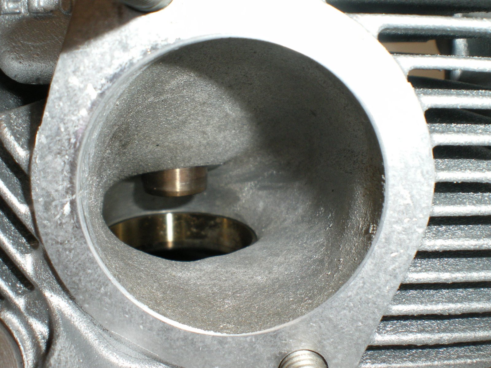
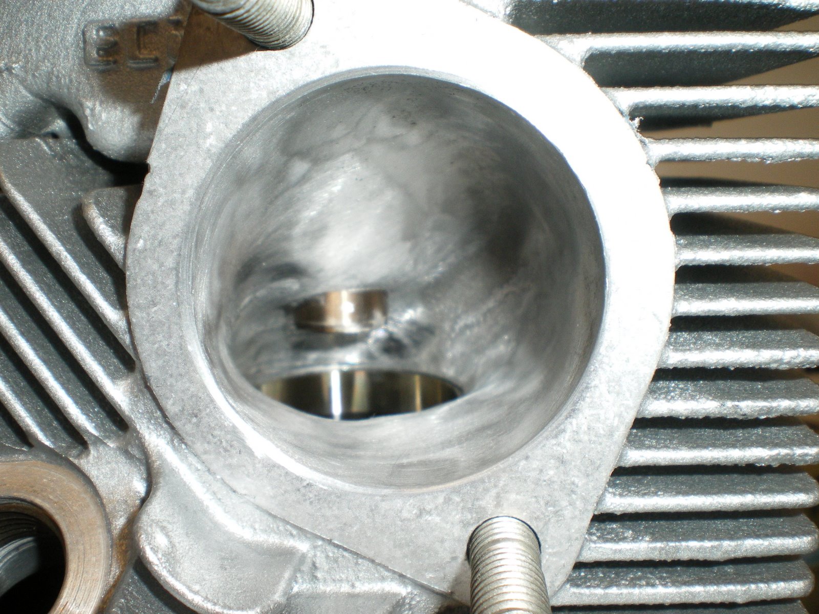
Next I am doing some grinding on the intake and exhaust ports. I have taken pictures of the sand casting in the ports and some of it is pretty rough. I have gotten cylinders from Ly-Con before and there porting is a work of art. They also produce the power as well. I just wanted to grind out imperfections and blend it all smooth. I could not reach all of the areas as you have to have some special grinding wheels to get in all of tight spots. I got about 80% of each port. I also had to be careful not to grind the seat for the valves. That would be very very bad. After I ground each cylinder I would clean it up and then lap the valves to the seats.
I talked with Ken Tunnel once about porting cylinders. He said all of his dyno testing indicated that the Lycoming cylinder worked out the best for porting. It always made more power. He has done Superior and ECI and indicated they never made the same power as Lycoming. I was in the shop one day getting my cylinders and he had a set ready to go for Sean Tucker for his Oracle bi-plane. They were Lycoming. Not saying ECI is bad, but something about there port design does not let the air flow the same. Call it BS but he has hard dyno testing to prove it. My cylinders with all of the mods to the engine should get me over 190 hp. If it puts out 195 with the 4-1 exhaust and the ram air cowling, I would be really happy.
I read up on lapping valves and there is not much too it. I purchased all of the items to lap valves at the local auto shop for about 20 bucks. You get some fine lapping compound, a lapping tool which is two suction cups on a stick, and a buncn of rags. I used some hose and extended the lapping tool so that it would stick up out of the cylinder a ways.
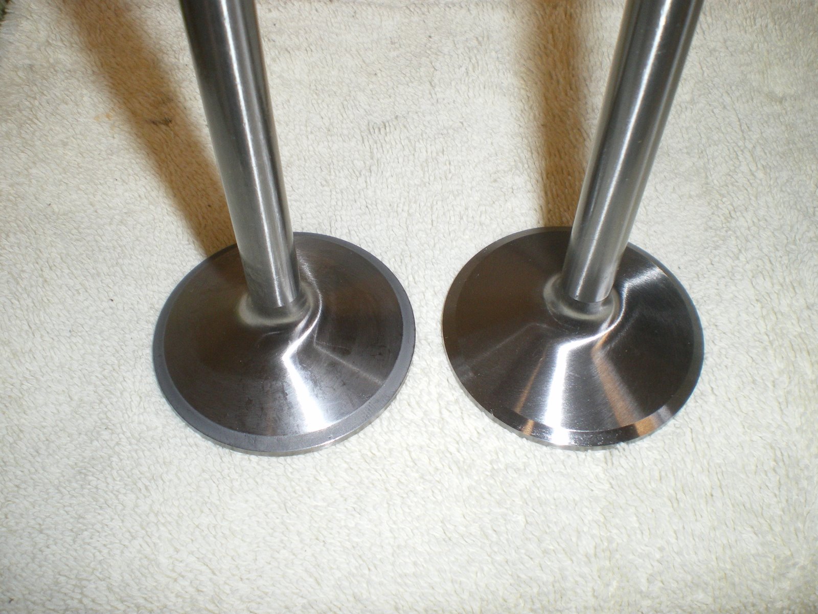
The valves in the cylinder cannot be mixed up. One is big (intake) and one is small (exhaust). I installed one on the end of the lapping tool, put compound on the seat of the valve , greased the stem and then installed it in the cylinder. I then set the cylinder up on the bench (inverted) let it lean against my chest. I then would spin the lapping tool back and forth like you are trying to start a fire. You need to hold a little down pressure as well. You can hear the valve lapping as it grinds. The grinding will start to go away and you will hear more of a smearing noise (you can feel it as well). This tells you that the valve is lapped and it completely seated in the valve seat. Take the valve out and clean it all up. Clean the seat as well. I then marked the cylinder a color and the both valve went into a valve box that was also marked the same color. This system will keep me from mixing up vavles cylinder to cylinder. Also when you look at the valves, you can see a slight graying of the valve where it hit the seat. The lapping compound it black and this help dye the area as it is ground down.
I purchased a Lycoming valve spring compressor from US Tools for 60 bucks. When I get that I will start putting the cylinders together for good and mounting them on the lower half of the engine.
After the top was painted I started on the bottom. Having problems with the top I had the local paint shop put some of my enamel in a spray can. They take my paint and put it in a spray can. It already has the solvents in it and it makes clean up a snap. I masked off the top and the lower portions so paint would not get on then and then took the cylinders outside and spray each one individually. They came out nice.
Next I am doing some grinding on the intake and exhaust ports. I have taken pictures of the sand casting in the ports and some of it is pretty rough. I have gotten cylinders from Ly-Con before and there porting is a work of art. They also produce the power as well. I just wanted to grind out imperfections and blend it all smooth. I could not reach all of the areas as you have to have some special grinding wheels to get in all of tight spots. I got about 80% of each port. I also had to be careful not to grind the seat for the valves. That would be very very bad. After I ground each cylinder I would clean it up and then lap the valves to the seats.
I talked with Ken Tunnel once about porting cylinders. He said all of his dyno testing indicated that the Lycoming cylinder worked out the best for porting. It always made more power. He has done Superior and ECI and indicated they never made the same power as Lycoming. I was in the shop one day getting my cylinders and he had a set ready to go for Sean Tucker for his Oracle bi-plane. They were Lycoming. Not saying ECI is bad, but something about there port design does not let the air flow the same. Call it BS but he has hard dyno testing to prove it. My cylinders with all of the mods to the engine should get me over 190 hp. If it puts out 195 with the 4-1 exhaust and the ram air cowling, I would be really happy.
I read up on lapping valves and there is not much too it. I purchased all of the items to lap valves at the local auto shop for about 20 bucks. You get some fine lapping compound, a lapping tool which is two suction cups on a stick, and a buncn of rags. I used some hose and extended the lapping tool so that it would stick up out of the cylinder a ways.
The valves in the cylinder cannot be mixed up. One is big (intake) and one is small (exhaust). I installed one on the end of the lapping tool, put compound on the seat of the valve , greased the stem and then installed it in the cylinder. I then set the cylinder up on the bench (inverted) let it lean against my chest. I then would spin the lapping tool back and forth like you are trying to start a fire. You need to hold a little down pressure as well. You can hear the valve lapping as it grinds. The grinding will start to go away and you will hear more of a smearing noise (you can feel it as well). This tells you that the valve is lapped and it completely seated in the valve seat. Take the valve out and clean it all up. Clean the seat as well. I then marked the cylinder a color and the both valve went into a valve box that was also marked the same color. This system will keep me from mixing up vavles cylinder to cylinder. Also when you look at the valves, you can see a slight graying of the valve where it hit the seat. The lapping compound it black and this help dye the area as it is ground down.
I purchased a Lycoming valve spring compressor from US Tools for 60 bucks. When I get that I will start putting the cylinders together for good and mounting them on the lower half of the engine.
Saturday, July 19, 2008
Installing the sump
After all of the assy case stuff is where it needs to be, I installed the sump. I have already installed the screen and plug, sniffle valve and oil drain valve prior to this. I checked over my safety wire jobs on the bottom bolts and got to putting the gasket sealant on the case. I also installed the 6 studs that go into the sump in the area under the cylinders. There is studs here so you can use nuts in the confined space instead of using bolts. There is sixteen bolts and 6 nuts to hold the sump down. I had to get some of my own bolts since they were not in the kit. I called Aerosport and they are sending some ASAP but my grade 8 bolts 1 inch long will do fine in this spot. I took some precaution when I installed the studs into the sump. They were an extremely tight fit and I was afraid of breaking the stud off trying to get it down into the threads with the double nuts on. I took a tap and tapped out the all six holes. I know they want a tight fit so the nut does not turn when you tightnen it down. I used some high strength Locktite on the threads and installed them. I did not torque these nuts down until the next day. I only had one turn on me and I marked it. I will check it later and see how it goes.
Installing all of the assy drives.
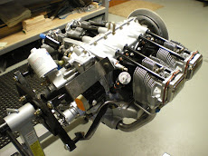
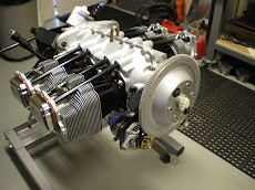
I installed the vac pump, gov drive, and fuel pump today. I tried to see if the fuel pump diaphragms were ethonal compatible but Tempest says they are not. I looked for the marine version of this style of pump thinking someone has already figured this out but I came up with nothing. I installed the pump now anyways because it is easy to get at and you can see what you are doing. The pump bolts are hard to get started and you have to have a octopus to hold all of the things that need to be held to get it installed. Why some one has not come up with a little bit of a different mounting style is beyond me. You have to install the bolts thru the pump first. Then you get the gasket down and in place. You then set the pump down in making sure the arm gets on top of the plunger in the assy case. You have to hold the pump away from the case about 1/4" so that the bolts go in straight. Make sure the fuel pump gear lobe is at the highest postion so there is very little spring pressure to overcome on the fuel pump arm. Once you get the bolts started you then tighten it down evenly making sure the arm does not come off to one side. It's easier to do it when the engine is upright and the oil sump is off. I change one on my RV-6 with the engine on it was a major job. I was almost to the piont of yanking whole engine off to get at it. I ended up having to do it twice because of the gasket not seating correctly and I had a small leak on the back of the engine. The govenor and vac pump drives are straight forward. Just pay attention to how the spacer washer is supposed to go and the vac pump gets a seal on the outside as the gov does not because you have a seal with the gaskets to get oil to the drive shaft. You can't interchange the drives since they are different sizes and lengths. I got all the bolts/nuts torqued and then I safetied wire the fuel pump bolts. DO THIS NOT WITH THE MAGS OFF. It's much more easier to get all the wires.
Installing assy case.
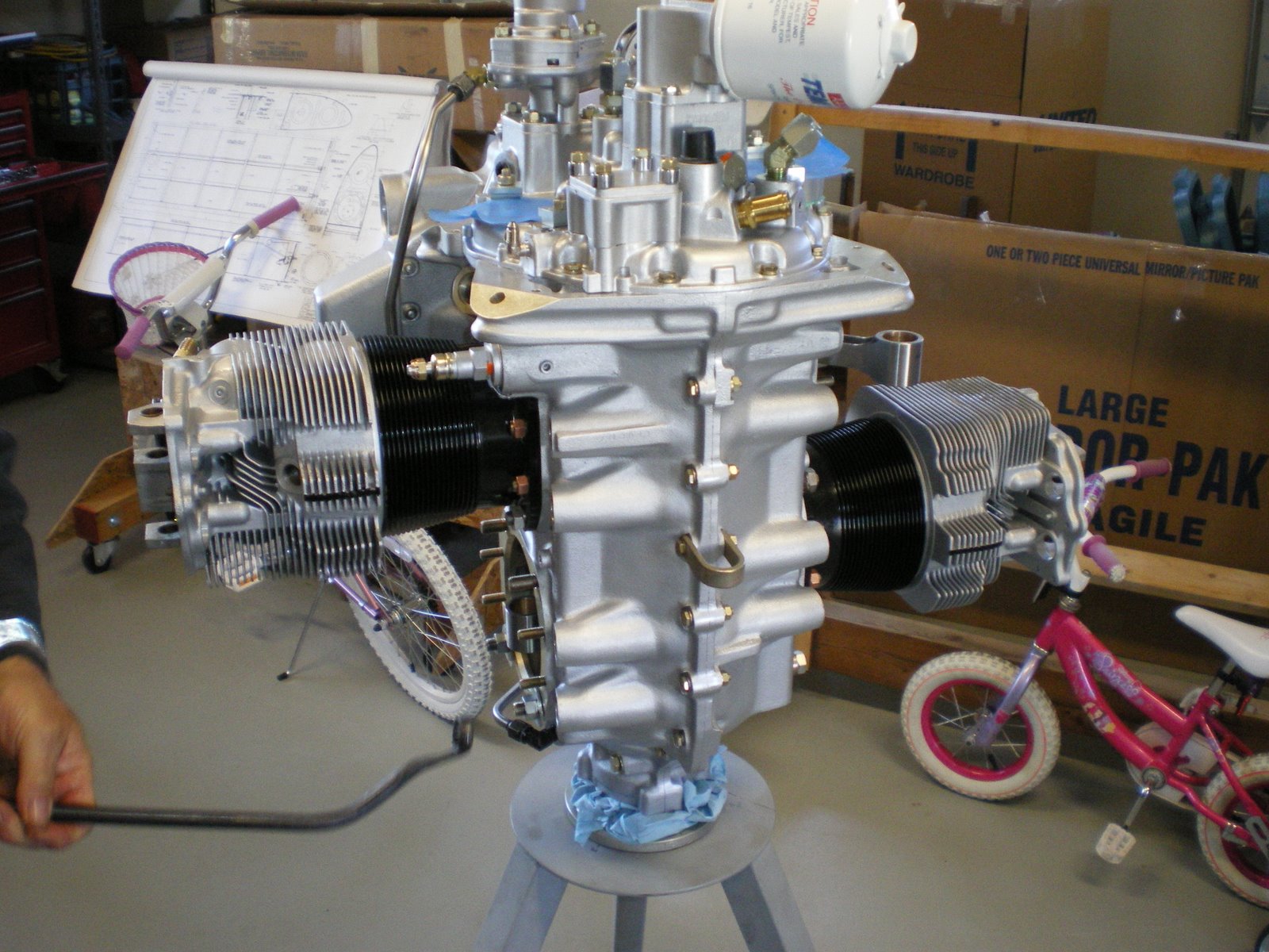
I installed the assy case. I made sure all of my timing marks were lined up, all of the nuts were safetied wired, tabs bent over on the idler shaft nuts, crankcase gear retainer in place. Fuel pump plunger is installed and lubed up. I got the gasket ready and put Locktite gasket sealer on both sides. I installed the assy case down over the tach shaft and then made sure the oil pump drive shaft lined up with the crankgear slot. I lowered it down into place and everything fit. I installed all of the 1/4 bolts that bolt it all down and torqued to 96 in/lbs. After I got this all done and started putting on the assy, I got a e-mail from a gentleman also building a ECI titan. He torqued his oil pump body nuts down to 204 in/lbs and one of his studs broke! The torque setting is more than Lycomings 150 in/lbs. It's wrong and ECI is going to get this resolved. I torqued mine a little less but over 150 in/lbs due to the holes not lining up with the castle nut. I tried combos of washers and different nuts but nothing came close. I even tried to move the stud but that was asking for disaster. I remember torquing one to 180 in/lbs to get it right and the rest were 160-170 in/lbs. This is close to the setting. The standard torque for those size and thread of bolts is 204 in/lbs. The mag studs are the same size and they are torqued to that setting. Why his stud broke is a good question. It sounds like ECI is going to take care of him and get him a new case and change the valve in the manual. I was glad to here that they took good care of him and I have always been happy with their service.
Subscribe to:
Posts (Atom)























.JPG)